
Product Short Description
Product Brief Introduction
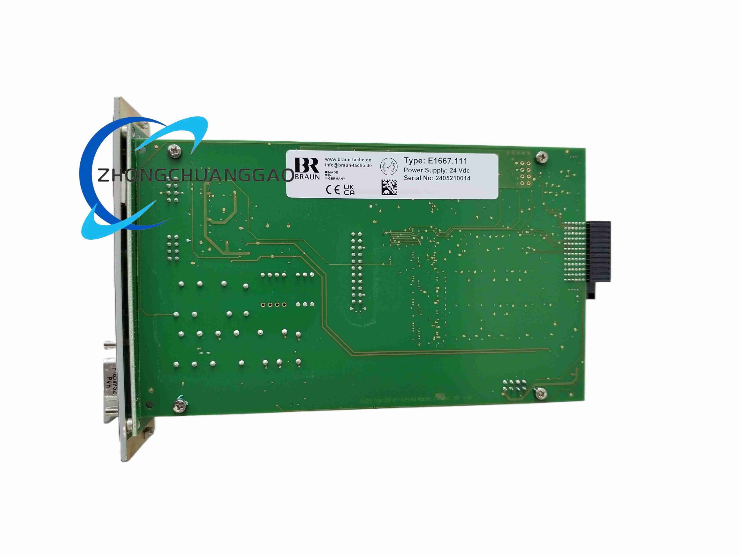
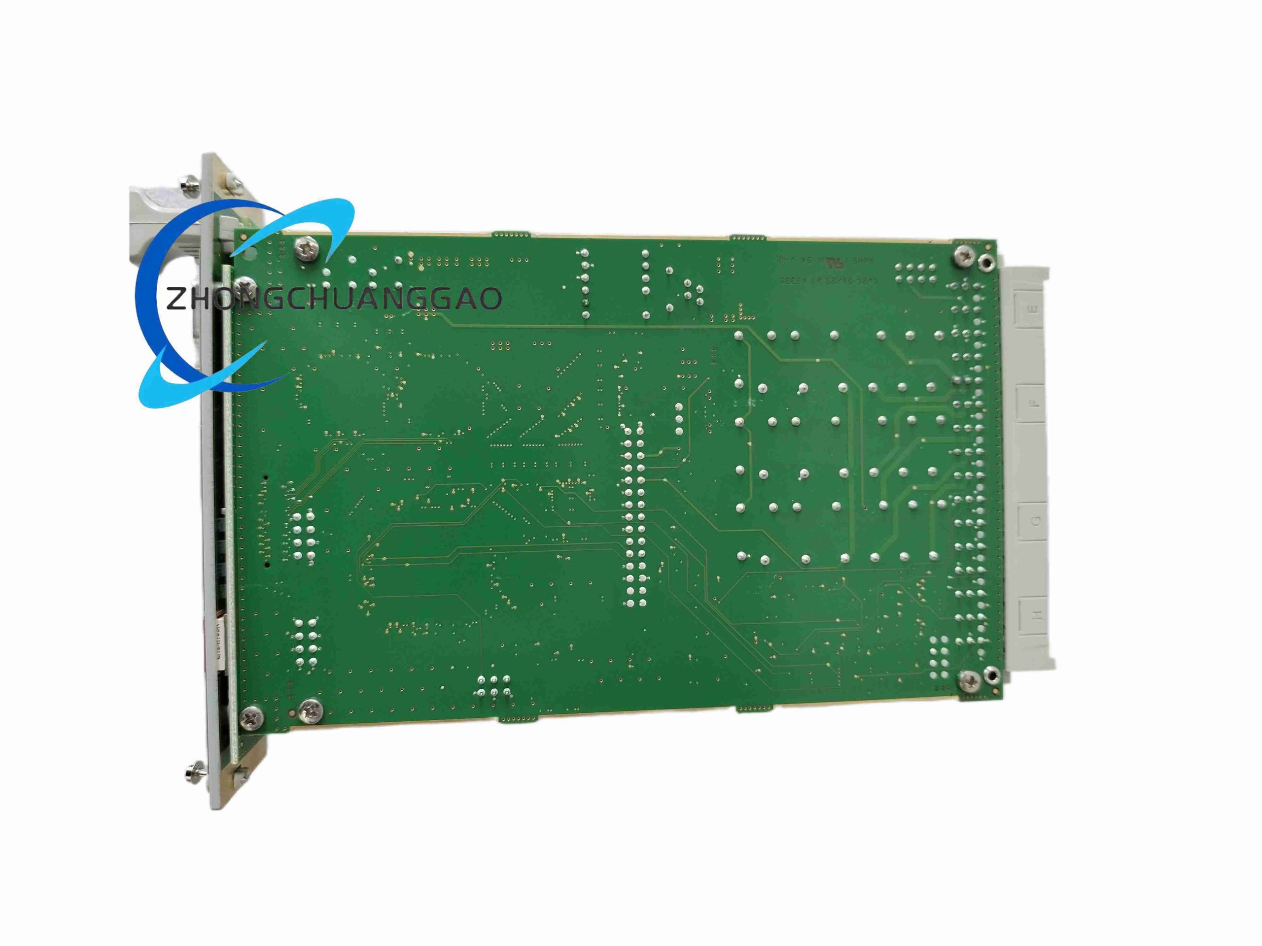
BRAUN E1667.111 is a safety-critical DIN rail mounted speed monitoring and overspeed protection module complying with IEC 61508 SIL3 safety standard, specially designed for high-speed rotating machinery such as steam turbines, gas compressors, large fans and generators. It receives pulse signals from magnetic speed pick-up sensors, calculates real-time rotational speed, executes multi-stage overspeed trip protection and provides analog speed output signal for DCS system acquisition.
Description
Core Technical Specifications
- Speed Measurement Electrical Parameters
- Input Sensor Signal Type: Magnetic passive speed probe pulse signal, frequency range 0.1 Hz ~ 10 kHz
- Measurable Rotational Speed Range: 0 ~ 20,000 RPM adjustable full scale
- Speed Calculation Sampling Cycle: Minimum 5 ms high-speed pulse interval measurement
- Measurement Accuracy: ±0.1% full scale speed error
- Analog Output Signal: Isolated 4–20 mA current output corresponding to full speed range
- Safety Trip Relay Output: Two independent fail-safe normally closed safety trip relays, SIL3 rated contact capacity
- Power & Safety Parameters
- Dual Power Supply Compatibility: 24 VDC ±10% low voltage DC power or 100–240 VAC 50/60 VAC mains power
- Total Power Consumption: ≤15 W maximum operating power
- Safety Voting Logic Configurable: 1oo2, 2oo2, 2oo3, 3oo3 sensor signal voting mode for multi-probe redundant systems
- Automatic Self-Test Cycle: Every 2 hours full internal circuit self-diagnosis, fault code stored in non-volatile memory
- Safety Certification: IEC 61508 SIL3, IEC 61511 process safety standard certified
- Mechanical & Environmental Parameters
- Mounting Standard: 35 mm top hat DIN rail single module width
- Overall Dimensions: 127 mm × 38 mm × 203 mm
- Net Weight: 650 g
- Operating Temperature Range: -40°C ~ +70°C industrial wide temperature cabinet environment
- Vibration Resistance: 10–500 Hz frequency band, 5 g continuous vibration tolerance
Function Features
- Working Principle: Multiple magnetic speed sensors generate pulse signals proportional to rotating equipment shaft speed; internal high-speed counter circuit measures pulse period to calculate real-time RPM value; configurable overspeed threshold comparison logic triggers fail-safe relay trip output when speed exceeds set safety limit; dual redundant signal acquisition channels implement safety voting logic to avoid single sensor failure false trip; analog isolation circuit converts speed value to standard 4–20 mA signal for remote DCS monitoring
- Multi-stage independent overspeed threshold setting: pre-alarm warning threshold, primary overspeed trip threshold, secondary emergency shutdown threshold three-level protection logic
- Front panel digital LED RPM display, button parameter setting menu without auxiliary programming software
- Built-in sensor wire breakage short-circuit fault detection, real-time fault alarm output
- Fail-safe circuit design: relay contact disengage to trigger equipment shutdown when module loses power or internal circuit fails
- Isolated analog output channel, no ground loop interference with plant DCS analog input modules
- Configurable external trip voting input terminals to link other safety protection signals for joint unit shutdown
Material Composition
- Outer Housing: Flame-retardant PA66 plastic DIN rail housing, UL94 V0 fire rating
- Internal PCB: Multi-layer safety-grade isolation circuit board with double-sided conformal insulation coating
- Safety Relay Components: SIL3 rated hermetically sealed safety relays with gold-plated contact points
- Front Display Window: Impact-resistant polycarbonate transparent protective cover for LED digital screen
- Terminal Block Hardware: Spring clamp gold-plated wiring terminals for vibration-resistant industrial wiring
Structural Characteristics
- Standard single-width DIN rail snap mounting structure with integrated locking buckle
- Front panel layout: digital RPM display, four parameter setting buttons, fault status LED indicator, D-SUB communication interface
- Rear panel separated terminal block zones: sensor signal input terminals, power supply terminals, safety relay trip output terminals, analog signal output terminals independent partition layout
- Internal reinforced isolation barrier between safety circuit and analog signal circuit to eliminate cross-circuit interference
- Integrated passive heat sink metal strip inside housing for natural heat dissipation without cooling fan
- Removable transparent front protective cover to prevent accidental misoperation of parameter buttons in production workshop
Application Scenarios
- Thermal power plant steam turbine/generator overspeed safety protection system
- Petrochemical large centrifugal compressor, axial fan speed monitoring and trip protection
- Natural gas pipeline compression station high-speed turbo compressor safety interlock
- Steel plant large industrial exhaust fan, boiler induced draft fan overspeed protection
- Hydropower station water turbine generator rotational speed safety monitoring
Installation Requirements
- Install on standard 35 mm DIN rail inside safety control cabinet, locking buckle fully engaged against cabinet vibration
- Separate sensor signal wiring from high-current power cable trunking, minimum 20 cm wiring distance to avoid pulse signal interference
- Magnetic speed probe shield cable single-end grounding at module terminal side, shield layer not grounded at sensor shaft end
- Safety trip relay output wiring must use dedicated fire-resistant control cable, contact load current cannot exceed rated relay capacity
- Cabinet internal ambient temperature must not exceed +70°C; install cooling fan if cabinet heat accumulation occurs
- Parameter setting must be completed before equipment startup, record all threshold values for maintenance file archiving
Operation & Maintenance Precautions
- Safety parameter modification requires dual maintenance personnel authorization to avoid accidental safety threshold misconfiguration
- Execute module self-test function monthly during equipment regular maintenance to verify internal safety circuit integrity
- If sensor fault alarm triggers, inspect speed probe mounting clearance and signal cable breakage
- Do not replace internal safety relays with non-SIL3 rated alternative components; safety certification will be invalidated
- Avoid installation near frequency converter high-frequency interference sources; signal distortion causes inaccurate speed measurement
- After long-term shutdown over 6 months, perform full module functional test before rotating equipment restart operation
Reviews
There are no reviews yet.