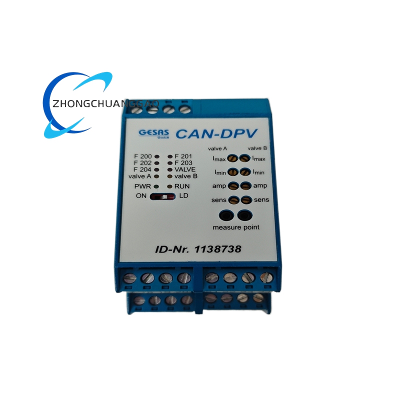
Product Short Description
Technical Specifications:
- Communication Protocol: CANopen (DS 301 V4.02)
- Output Channels: 4 independent analog outputs
- Output Signal: 0–10 VDC or 4–20 mA (selectable per channel via DIP switch)
- Output Resolution: 12-bit DAC (4096 steps)
- Supply Voltage: 24 VDC (nominal, 18–30 VDC range)
- Current per Channel: Up to 50 mA (voltage mode) or loop-powered (current mode)
Description
Functional Features:
- CANopen PDO mapping: RPDO for setpoint, TPDO for actual value and fault status
- Ramping function: Configurable acceleration/deceleration ramps per channel
- Fail-safe output: Configurable output on communication loss (hold last value / zero / max)
- Diagnostics: Per-channel overcurrent, short-circuit, open-loop detection
Performance Parameters:
- Update rate: 10 ms (100 Hz) per channel
- Linearity: ±0.5% of full scale
- Operating temperature: -20°C to +60°C
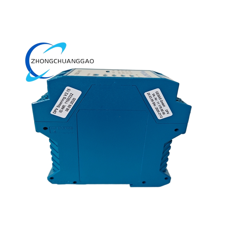
- Dimensions: 90 mm × 100 mm × 65 mm (W × H × D)
- Weight: 280 g
Material Composition: Aluminum extrusion housing, FR-4 PCB, gold-plated CAN connector, spring-clamp terminal blocks
Structural Features: DIN rail (35 mm) mounting; M12 or DB9 CAN connector; 4 sets of 3-wire terminal blocks (common, signal, feedback); 4 LED indicators per channel
Working Principle: The module receives setpoint values via CANopen TPDO/RPDO. The internal 12-bit DAC converts the digital value to an analog voltage or current output. The output drives the proportional valve solenoid. Actual valve position feedback (if 4–20 mA with live zero) is read back and transmitted via CANopen.
Advantages:
- 4 independent channels on a single CAN node
- Dual output mode (voltage/current) per channel provides flexibility
- Deterministic 10 ms update rate for closed-loop process control
Applicable Industries: Hydraulic/pneumatic valve control, chemical dosing, HVAC damper actuation, irrigation systems, test rigs
Installation Requirements:
- Mount on DIN rail inside control cabinet
- Use 24 VDC regulated power supply (minimum 500 mA total)
- Terminate CAN bus with 120 Ω at both ends
Usage Notes:
- Set output mode (0–10 V or 4–20 mA) via DIP switch before powering on
- Configure fail-safe behavior per application requirements
- Verify valve impedance matches output current capability
-500x500.jpg)
Reviews
There are no reviews yet.