
Product Short Description
Product Brief Overview
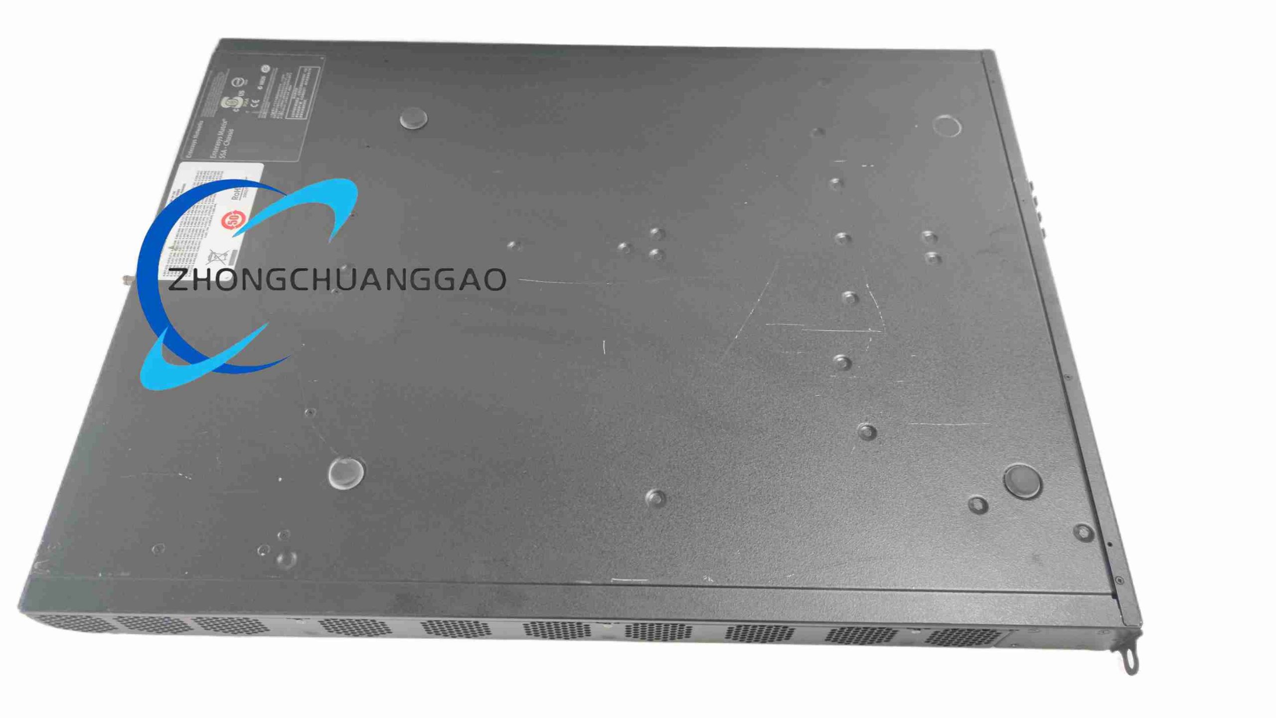
This hardware unit is a core member of Enterasys Secure Networks S-Series enterprise switching platform, engineered as a dual-purpose device supporting standalone rack deployment and hot-pluggable blade installation inside S-Series modular chassis systems. It integrates an embedded internal power supply, delivering non-blocking wire-speed packet forwarding performance alongside comprehensive built-in enterprise network security features, multi-layer traffic scheduling, and stable long-term continuous operation.
Description
Hardware Port Configuration
- Downlink copper interfaces: 18 units of 10/100/1000BASE-T auto-sensing RJ45 gigabit ports, supporting automatic duplex and speed matching with connected terminal equipment
- High-speed uplink expansion slots: 4 SFP+ 10GBASE-X fiber transceiver slots for long-distance fiber uplink connection to core network switches
- Local debugging auxiliary port: Micro-USB console port for offline device configuration and fault troubleshooting without network access
- Physical control components: Dedicated hardware offline switch and one-key system restart button for rapid equipment reset during network failures
- Visual status indicator system: Independent LED indicator lights for power supply status, port link detection, data transmission activity, global system fault alarm, and stacking cluster working mode
Switching Performance Parameters
- Total switching fabric capacity: 36 Gbps full-duplex non-blocking throughput, no internal bandwidth bottleneck under full port concurrent load
- Wire-speed packet forwarding rate: 2 million packets per second processing capability for each gigabit port
- MAC address storage table depth: 16,384 independent MAC address entry storage space for terminal device identification
- VLAN resource capacity: Compatible with up to 4,096 IEEE 802.1Q tagged virtual local area networks for logical network isolation
- Static routing entry limit: Supports storage of 512 IPv4 static routing table entries to realize inter-VLAN cross-segment data transmission
- Dynamic shared packet buffer memory: 12MB unified cache space allocated dynamically to all ports based on real-time traffic load
Electrical Power Specifications
- Input alternating current standard: Wide-range AC input covering 100V to 240V, compatible with 50Hz and 60Hz global mains power grids
- Maximum overall power consumption: 40W when all 18 copper ports and 4 SFP+ uplink slots run at full transmission load
- Power supply integration design: Built-in integrated power conversion circuit, eliminating the need for external power adapters or power bricks
- Backplane power compatibility: Standard power interface matching the internal backplane of Enterasys S-Series modular chassis for blade power supply
Environmental Operating Parameters
- Normal working ambient temperature range: 0 degrees Celsius to +50 degrees Celsius
- Long-term storage temperature range without power supply: -40 degrees Celsius to +70 degrees Celsius
- Tolerable relative humidity range: 5% to 95% relative air humidity, operation prohibited under condensing water vapor conditions
- Global electromagnetic compliance certifications: CE industrial certification, FCC Class A electromagnetic interference standard, fully RoHS hazardous substance restricted compliant
Physical Dimension & Weight Data
- External overall physical size (Height × Width × Depth): 44mm × 440mm × 305mm
- Net equipment weight distinction: 1.15kg for blade-only module variant; 2.5kg for standalone rack-mounted complete switch unit
- Standard rack form factor: 1U rack height, fully compatible with all standard 19-inch industrial server cabinet installation guide rails
Core Function Features
Layer 2 Basic Switching Functional Modules
- Full IEEE 802.3 standard compliance for all copper ports, supporting automatic negotiation of full-duplex and half-duplex transmission modes
- Multi-type VLAN support system: IEEE 802.1Q tag-based VLAN, physical port-based isolated VLAN, dedicated voice VLAN optimized for IP telephone voice data transmission
- Link bandwidth expansion technology: Static and dynamic LACP IEEE 802.3ad link aggregation groups, bundling multiple physical ports into one logical high-bandwidth uplink channel
- Redundant network loop prevention protocol suite: STP, RSTP and MSTP spanning tree protocols to eliminate broadcast loop faults in redundant network topology
- Hardware port mirroring function: Bidirectional ingress and egress traffic data capture for offline network anomaly diagnosis and data flow analysis
Layer 3 Routing & QoS Traffic Management Capabilities
- Basic IPv4 static routing function, configurable default gateway parameters, native inter-VLAN routing to realize data exchange between isolated logical network segments
- Complete multi-level QoS traffic scheduling architecture: 8 independent hardware priority queues allocated to every physical port; traffic classification based on DSCP digital service code and 802.1p layer 2 priority tags; dual scheduling algorithms including strict priority queuing and weighted round-robin for differentiated service delivery
- Precise port bandwidth control: Configurable ingress and egress traffic rate limitation; automatic suppression mechanism for broadcast and multicast data storms to avoid network resource exhaustion caused by abnormal broadcast packets
Enterprise-Grade Network Security Functional Modules
- Physical port access security mechanism: Static MAC address binding, configurable dynamic MAC address learning quantity limit to prevent unauthorized terminal access
- Triple binding access control rule: Simultaneous matching of IP address, MAC address and physical port number to restrict illegal device network access
- Multi-layer packet filtering system: MAC address filtering list, Layer 2 to Layer 4 ACL access control lists supporting packet filtering based on source address, destination address, port number and protocol type
- 802.1X port authentication protocol: Port-based network access control, compatible with RADIUS remote authentication server for centralized user identity verification
- Built-in abnormal traffic intrusion detection logic, automatic system log recording and visual fault alarm for potential network attack behaviors
- Encrypted remote equipment management channels: SSH encrypted command line management, HTTPS encrypted web graphical management interface, SNMPv3 encrypted network monitoring protocol to avoid plaintext management data interception
Equipment Operation Management & Maintainability Functions
- Multi-channel equipment management access methods: Local Micro-USB console offline configuration port, graphical web management interface, text CLI command line interface, native compatibility with Enterasys NetSight unified enterprise network management platform for batch equipment monitoring and configuration
- System configuration file management: Local storage of complete device configuration files, one-click backup and recovery functions, remote firmware online upgrade via TFTP and FTP transmission protocols
- Real-time system operation data recording: Continuous storage of system running logs, automatic recording of all fault alarm events, long-term statistics of port real-time and cumulative data traffic volume
- Hot-swappable hardware blade design for chassis installation mode: Module replacement can be executed without cutting off the power supply of the entire chassis system, greatly reducing network downtime during equipment maintenance and upgrade operations
Material Composition & Structural Characteristics
Main Raw Material Construction
- Outer equipment casing: High-strength cold rolled steel metal shell processed with matte black anti-corrosion electrostatic spray coating, resisting surface scratch damage and industrial environment dust corrosion
- Internal circuit carrier substrate: Multi-layer rigid FR4 glass fiber epoxy printed circuit board with high temperature resistance and stable electrical insulation performance
- Port connection hardware components: Nickel-plated copper RJ45 port elastic contact pieces and gold-plated SFP+ slot conductive terminals, minimizing contact resistance and resisting long-term oxidation
- Heat dissipation auxiliary structure: Integral stamped metal heat sink fins tightly attached to main switching chip surface, passive natural convection heat dissipation without built-in cooling fans
- Mounting accessory materials: Electroplated steel rack mounting brackets, stainless steel fixing screws, high toughness plastic port dust protection plugs
Detailed Structural Feature Description
- Front panel integrated layout: All RJ45 downlink ports, SFP+ uplink slots, LED indicator array, Micro-USB console port and physical control buttons are concentrated on the equipment front panel for convenient daily visual inspection and wiring operation
- Rear panel simplified design: Only integrated power input socket and grounding terminal reserved on the rear shell, no redundant external expansion interfaces
- Internal modular circuit separation: Power supply conversion circuit board, main switching control motherboard and port interface sub-boards adopt independent layered layout inside the shell, separated by metal isolation baffles to reduce internal electromagnetic signal interference
- Anti-static structural design: Continuous metal grounding path from front panel port housing to rear grounding terminal, effectively exporting static electricity generated by plugging and unplugging network cables to protect internal core chips from static breakdown damage
- Stacking compatibility reserved structure: Dedicated stacking signal circuit layout on the mainboard, supporting physical stacking connection with multiple identical SSA-G1018 series switches to form a unified virtual switching cluster with centralized management
Installation Requirements
Rack Mount Installation Standards
- Select standard 19-inch industrial server cabinet with intact horizontal mounting guide rails
- Fix matching metal mounting brackets to both left and right sides of the equipment shell using supplied stainless steel screws
- Place the switch horizontally into the cabinet guide rails, adjust horizontal balance, then fasten bracket fixing screws on the cabinet front beam
- Maintain a minimum vertical clearance of 50mm above and below the equipment shell to ensure smooth natural convection heat dissipation, avoid stacking other heat-generating electrical equipment directly above or below the switch
- Connect the rear panel grounding terminal to the cabinet general grounding busbar using dedicated grounding copper wire to complete anti-static and lightning protection grounding connection
Chassis Blade Installation Standards
- Cut off the power supply of the Enterasys S-Series modular chassis before initial blade installation or replacement
- Hold the blade module by the two side metal handles, keep the module horizontal, align the internal golden finger connector of the blade with the chassis backplane slot
- Push the blade steadily inward until the front panel of the blade fits tightly with the chassis slot panel, lock the side fixing handles to complete mechanical fixing
- Restore chassis power supply, observe front panel power LED indicator, confirm normal power-on startup without fault alarm lights
- Complete basic network configuration through console port after successful power-on, verify normal data forwarding function of all ports
Wiring Installation Specifications
- Use Category 5e or Category 6 shielded twisted pair copper network cables for RJ45 port wiring; select matching industrial-grade single-mode or multi-mode fiber jumpers for SFP+ fiber uplink slots
- Avoid bending network cables and fiber jumpers with bending radius less than the minimum standard specified by the cable manufacturer, prevent internal wire core breakage and signal attenuation
- Classify and separate power supply wiring and signal network wiring inside the cabinet, maintain a horizontal spacing of at least 10cm between the two types of wiring to reduce electromagnetic crosstalk interference
- Install plastic dust plugs on all unused RJ45 ports and SFP+ slots to prevent dust, metal debris and moisture from entering the port interior and causing short-circuit faults
Application Scenarios
Enterprise Campus Core Distribution Networks
Deployed as building floor distribution switches inside office building wiring closets, connecting office desktop PCs, IP phones, wireless AP access points, printing terminals and building monitoring equipment, realizing logical network isolation between different departments through VLAN configuration, supporting differentiated QoS scheduling for voice, video and office data traffic to guarantee smooth operation of enterprise daily office business.
Small & Medium Data Center Edge Access Nodes
Installed on the top of server racks inside small-scale enterprise data centers, responsible for providing gigabit access for storage servers, application servers and database hosts; utilize 10G SFP+ fiber uplink ports to establish high-bandwidth connection with data center core layer switches, adopt multi-layer ACL security rules to isolate server clusters with different service levels and prevent unauthorized cross-cluster data access.
Industrial Automation Control Networks
Applied to industrial factory workshop control cabinet networking scenarios, matched with industrial PLC controllers, servo drive equipment, industrial touch screen HMI terminals and production line sensor data acquisition equipment; comply with industrial electromagnetic anti-interference standards, support broadcast storm suppression and low-latency real-time data forwarding to ensure stable and uninterrupted transmission of production line real-time control signals, avoid production line shutdown faults caused by network congestion or broadcast loops.
Government Institution & Public Service Office Networks
Suitable for local government bureau office networks, school campus networks and hospital ward office networking environments; integrated comprehensive port security and 802.1X identity authentication functions, realizing strict access control of internal staff terminals and external visitor temporary equipment, record all equipment access logs for post-fault traceability, support encrypted remote management to prevent confidential government and medical data leakage through network interception.
Working Principle
The core working logic of Enterasys SSA-G1018-0652 is based on hardware ASIC switching chip packet forwarding architecture, divided into four sequential working stages: data receiving, data processing, data forwarding and data output.
- Data Receiving Stage: When data packets transmitted from terminal equipment arrive at the RJ45 copper port or SFP+ fiber port, the port physical layer transceiver chip completes analog electrical signal or optical signal demodulation, converts external transmission signals into digital bit stream data recognizable by the internal switching chip, then transmits the complete data packet into the shared dynamic packet buffer memory for temporary storage.
- Data Processing Stage: The core ASIC switching chip extracts key identification fields from the data packet header, including source MAC address, destination MAC address, VLAN tag label, source and destination IP address, transmission layer port number and priority tag information. The chip searches the pre-stored MAC address table, VLAN resource table and static routing table stored in on-board flash memory to match forwarding rules, simultaneously executes pre-configured ACL filtering, QoS priority marking, broadcast storm suppression and port security access control logic, discards illegal data packets that do not meet access rules directly in the buffer memory without subsequent forwarding processing.
- Data Forwarding Stage: For legal data packets passing all security and filtering rule checks, the switching chip determines the target physical output port according to the matched MAC address table or inter-VLAN routing table entry; if the destination MAC address entry does not exist in the MAC address table, the chip executes broadcast forwarding operation and copies the data packet to all ports belonging to the same VLAN segment. During forwarding scheduling, the chip distributes data packets to 8 hardware priority queues corresponding to the target port, and allocates transmission time slices according to pre-configured strict priority or weighted round-robin QoS scheduling algorithm to realize differentiated priority transmission of different service data streams.
- Data Output Stage: The port physical layer transceiver chip reads data packets from the corresponding priority queue buffer memory, completes digital bit stream modulation into electrical signals (copper ports) or optical signals (fiber ports), then transmits the modulated signal data packets outwards through connected network cables or fiber jumpers to the target receiving terminal equipment.
During the entire continuous working cycle, the main control CPU on the switching motherboard operates independently in parallel with the ASIC forwarding chip, responsible for receiving remote management configuration commands, updating MAC address tables and routing tables, recording system running logs and fault alarm information, detecting hardware port status changes, and executing firmware upgrade and system configuration backup tasks, ensuring coordinated operation of high-speed hardware packet forwarding and flexible equipment software management functions.
Use Precautions
Power Supply Usage Precautions
- Only connect the equipment power input socket to standard mains power sockets with complete grounding protection; do not use ungrounded extension cords or damaged power cables to supply power to the switch, avoid electric shock hazards and static damage to internal chips
- The equipment supports wide-range AC input, but frequent severe voltage fluctuation and instantaneous power surge will cause abnormal restart of the switch; install dedicated surge protection power strips or industrial power supply filters at the front end of the power input circuit in industrial power supply environments with unstable voltage
- Cut off the power supply completely before disassembling the equipment shell, replacing internal components or plugging/unplugging chassis blade modules; do not hot-plug the power input cable during normal equipment operation to prevent instantaneous power failure from damaging the flash memory storage chip and causing loss of equipment configuration files
Daily Operation & Wiring Precautions
- Regularly check the front panel LED status indicators during daily equipment operation; if the fault alarm LED is continuously lit, cut off non-critical terminal port connections in time, export system running logs for fault analysis, and eliminate abnormal traffic sources causing equipment alarms
- Do not plug or unplug network cables and fiber jumpers violently during equipment power-on operation; excessive pulling force will damage internal port elastic contact pieces and fiber core wires, leading to poor contact and intermittent data packet loss faults
- Keep the equipment installation environment dry and clean; avoid installing the switch in locations with high humidity, corrosive chemical gas, large amounts of floating dust or direct liquid splashing risks, prevent internal circuit board short-circuit and metal component oxidation corrosion damage
- Do not place heavy objects on the top surface of the equipment shell; excessive external pressure will deform the metal casing, squeeze internal circuit boards and chip components, causing circuit disconnection and permanent hardware damage
Maintenance & Upgrade Precautions
- Execute complete configuration file backup operation before all firmware version upgrade and equipment configuration modification operations, store backup configuration files in local offline storage equipment, to realize rapid configuration recovery if upgrade failure or configuration error occurs and causes equipment abnormal operation
- Firmware upgrade transmission must adopt stable wired local console port transmission or TFTP wired network transmission mode; wireless Wi-Fi transmission is prohibited for firmware upgrade file delivery, unstable wireless signal will cause incomplete firmware file transmission, leading to equipment boot failure and bricking fault
- Do not open the equipment metal shell for internal disassembly maintenance without professional industrial network equipment maintenance qualification; the internal circuit board contains high-voltage power conversion circuits and precision electrostatic-sensitive chips, unauthorized disassembly will cause electric shock hazards and permanent static breakdown damage to core components, and will void all original equipment manufacturer product warranty service rights
- Conduct regular quarterly equipment maintenance inspections: clean dust accumulated on front panel ports and shell heat dissipation fins with dry anti-static soft brushes, check the tightness of all wiring connectors and cabinet grounding wire connections, verify the normal lighting status of all port LED indicators, and clear redundant historical log files stored in equipment flash memory to avoid insufficient storage space affecting normal system operation
Reviews
There are no reviews yet.