Product Short Description
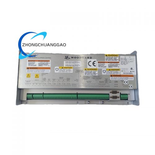
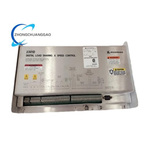
Woodward 5448-906 REVSPM-D10 is a digital electronic speed and load controller manufactured by Woodward, Inc. (a subsidiary of Hexatronic Group AB, headquartered in Fort Collins, Colorado, USA). This device serves as the primary governing system for industrial gas turbines, aeroderivative gas turbines, diesel engines, and steam turbines ranging from 1 MW to 100+ MW. It replaces the legacy analog 505/505E speed controllers and provides full digital control of engine speed, load sharing, synchronizing, and protection functions. The REVSPM-D10 revision denotes the tenth hardware revision of the REVSPM (Revised Speed/Load Module) product line.
Description
Model Series
Woodward 5400 Series Digital Speed/Load Controllers
Related models in the 5400 series include:
- Woodward 5448-101 — Base 5448 speed controller, single-input
- Woodward 5448-102 — 5448 with dual speed input
- Woodward 5448-201 — 5448 with load control and synchronization
- Woodward 5448-906 — 5448 with integrated PMG (Permanent Magnet Generator) input, REVSPM-D10 revision
- Woodward 5466 — Next-generation EasyGen-3500 controller (successor platform)
- Woodward 505E — Legacy analog speed controller (replaced by 5448 series)
- Woodward 505F — Legacy analog speed controller with fuel limiter (replaced by 5448 series)
Manufacturer
Woodward, Inc.
Hexatronic Group AB
Address: 1000 East Drake Road, Fort Collins, CO 80525, USA
Parent Company: Hexatronic Group AB, Drottninggatan 89, 111 60 Stockholm, Sweden
Technical Specifications
| Parameter | Specification |
|---|---|
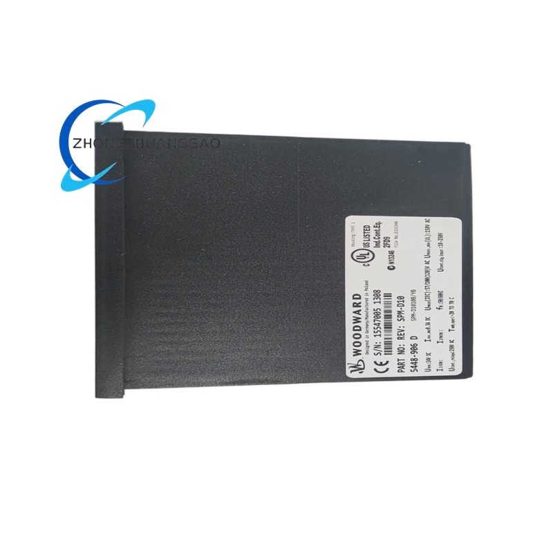
| Part Number | 5448-906 |
| Revision Level | REVSPM-D10 |
| Controller Type | Digital Microprocessor-Based Speed/Load Controller |
| Speed Input | Permanent Magnet Generator (PMG), 400 Hz to 1600 Hz, 15 VAC to 120 VAC |
| Speed Range | 0 to 110% of rated speed (50 Hz or 60 Hz base) |
| Speed Accuracy | ±0.03% of setpoint (steady state) |
| Speed Droop | 0% to 10% adjustable (isochronous to 10% droop) |
| Load Control Range | 0% to 100% of rated load |
| Synchronizing | Auto-synchronization with voltage, frequency, and phase matching |
| Control Outputs | 4 to 20 mA (fuel servo), 0 to 10 VDC (auxiliary), relay contacts (alarm/trip) |
| Analog Inputs | 4 to 20 mA (×4 channels), 0 to 10 VDC (×2 channels), RTD (×2 channels) |
| Digital Inputs | 24 VDC, opto-isolated (×12 channels) |
| Digital Outputs | 24 VDC, transistor (×8 channels), relay (×4 channels) |
| Communication Interfaces | RS-485 (Modbus RTU), RS-232, Ethernet (optional module) |
| Power Supply | 24 VDC nominal (18 VDC to 32 VDC range), 8 W maximum |
| Operating Temperature Range | -20°C to +60°C (-4°F to +140°F) |
| Storage Temperature Range | -40°C to +85°C (-40°F to +185°F) |
| Humidity Range | 5% to 95% RH, non-condensing |
| Altitude | Up to 3,000 m (10,000 ft) above sea level (derate above 1,000 m) |
| Vibration Tolerance | Per IEC 60068-2-6, 5g RMS, 10 Hz to 200 Hz |
| Shock Tolerance | Per IEC 60068-2-27, 15g, 11 ms half-sine |
| EMC Compliance | IEC 61000-6-2 (Industrial), IEC 61000-6-4 (Emission) |
| Enclosure Rating | IP54 (front panel), NEMA 4X (when panel-mounted) |
| Dimensions (W × H × D) | Approximately 146 mm × 197 mm × 120 mm (5.75 in × 7.75 in × 4.75 in) |
| Weight | Approximately 1.8 kg (4.0 lbs) |
| Certifications | CE, UL 508, CSA C22.2 No. 142, ATEX (optional) |
| Compliance Standards | ISO 8528 (Genset Control), IEC 60034, IEEE 1547, NFPA 85 |
Functional Features
- Permanent Magnet Generator (PMG) speed sensing — accepts variable frequency PMG input from 400 Hz to 1600 Hz, enabling operation across the full speed range without external tachometer
- Isochronous and droop speed control — switchable between 0% droop (isochronous) and 10% droop for single-machine or parallel operation
- Automatic load sharing — when multiple generators operate in parallel, the controller automatically adjusts fuel to maintain equal load distribution within ±1%
- Auto-synchronization — matches voltage magnitude, frequency, and phase angle before closing the breaker, with adjustable synchronizing time window of 0.1 s to 30 s
- Fuel limiting — programmable maximum and minimum fuel limit to protect the engine from overspeed or stall conditions
- Programmable acceleration/deceleration ramps — adjustable ramp rates from 0.1%/s to 100%/s for controlled startup and shutdown
- Engine protection — includes overspeed trip, underspeed trip, overtemperature trip, low oil pressure trip, and high exhaust temperature trip with configurable setpoints
- Governor mode switching — supports Speed Control, Load Control, and Isochronous modes selectable via front panel or remote signal
- Remote monitoring — RS-485 Modbus RTU interface enables remote reading of speed, load, fuel position, and alarm status from a SCADA system or HMI
- Event logging — internal non-volatile memory stores the last 256 events with timestamps for post-event analysis
Performance Parameters
| Parameter | Specification |
|---|---|
| Speed Control Accuracy (Steady State) | ±0.03% of setpoint |
| Speed Control Accuracy (Transient) | ±0.1% during load step change (0 to 100% load) |
| Load Control Accuracy | ±1% of setpoint |
| Frequency Regulation (Isochronous) | ±0.01 Hz at 50 Hz / ±0.012 Hz at 60 Hz |
| Response Time (Speed) | < 100 ms for 10% load step change |
| Analog Input Resolution | 16-bit ADC, 0.0015% of full scale |
| Analog Output Resolution | 12-bit DAC, 0.024% of full scale |
| Communication Baud Rate | 9600, 19200, 38400, 57600, 115200 bps (configurable) |
| Mean Time Between Failures (MTBF) | > 200,000 hours (per MIL-HDBK-217F) |
| Software Update | Field-upgradeable via RS-232 or USB (USB adapter optional) |
Material Composition
| Component | Material |
|---|---|
| Enclosure | Die-cast aluminum alloy (ADC12), powder-coated, RAL 7035 (light gray) |
| Front Panel | 1.6 mm anodized aluminum, laser-etched legend |
| PCB Substrate | FR-4 epoxy glass laminate, 4-layer, Tg ≥ 150°C |
| Connector Housings | Glass-fiber reinforced polyamide (PA66-GF30), UL 94 V-0 rated |
| Connector Contacts | Phosphor bronze, gold-plated (30 μin Au over 100 μin Ni) |
| Wire Terminals | Tin-plated copper alloy, screw-clamp type |
| Display | LED backlit LCD, 16 × 2 characters, operating range -20°C to +60°C |
| Potentiometers (if equipped) | Cermet trim potentiometer, sealed, 10-turn |
| Seals and Gaskets | Silicone rubber, 70 Shore A durometer |
| Conformal Coating | Acrylic conformal coating (per IPC-CC-830B) |
| Mounting Hardware | Stainless steel 304, passivated |
Structural Characteristics
- Form Factor: DIN rail or panel-mountable controller with integrated front panel interface
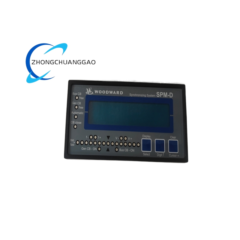
- Front Panel Layout:
- 16 × 2 character LCD display — shows speed, load, fuel position, mode, and alarm status
- 4 × push-button navigation keys — menu navigation, parameter adjustment, mode selection
- 2 × rotary potentiometers — speed setpoint and load setpoint (optional, depending on configuration)
- 6 × LED indicators — power, run, alarm, trip, sync, and communication status
- 2 × mini-DIN connectors — RS-485 and RS-232 communication ports
- 1 × DB-15 connector — analog I/O and digital I/O breakout
- Rear Panel:
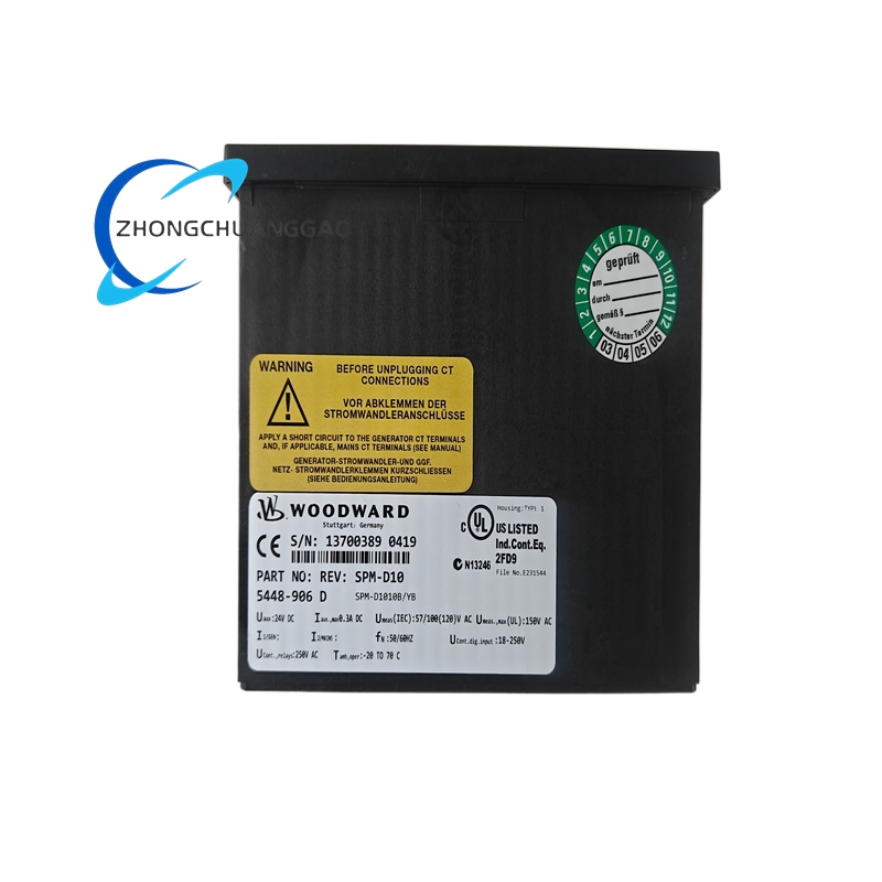
- 2 × 4-pin terminal blocks — PMG speed input (A+, A−, B+, B−)
- 1 × 8-pin terminal block — fuel servo output (4 to 20 mA)
- 2 × 6-pin terminal blocks — digital inputs and relay outputs
- 1 × 4-pin terminal block — 24 VDC power input
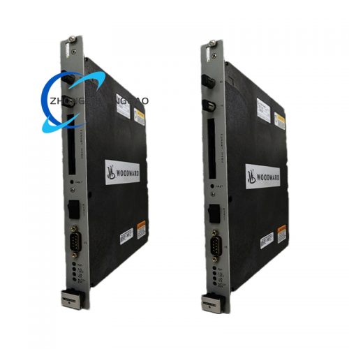
- Internal Layout:
- Main processor board — mounted vertically on the left side of the enclosure
- Power supply module — isolated DC-DC converter, mounted on the right side
- I/O terminal boards — removable plug-in modules for analog and digital I/O
- Communication module — removable RS-485/RS-232 board with opto-isolation
Working Principle
- Speed Sensing: The PMG (Permanent Magnet Generator) mounted on the engine shaft generates a three-phase AC voltage whose frequency is directly proportional to engine speed. The 5448-906 accepts this signal on the PMG input terminals (A+, A−, B+, B−) and measures frequency from 400 Hz to 1600 Hz
- Frequency-to-Speed Conversion: The internal microprocessor converts the PMG frequency to engine speed in RPM or Hz using the formula: Speed (RPM) = (Frequency × 60) / Number of PMG poles
- Error Calculation: The measured speed is compared against the speed setpoint (entered via front panel potentiometer or remote signal). The difference is the speed error signal
- PID Control: A digital Proportional-Integral-Derivative (PID) controller processes the speed error and generates a fuel demand signal (4 to 20 mA) proportional to the required fuel flow
- Fuel Servo Actuation: The 4 to 20 mA signal drives the fuel control valve servo motor, which adjusts the fuel rack position to increase or decrease fuel flow
- Load Control Mode: When in load control mode, the controller compares actual load (from a 4 to 20 mA load transducer) against the load setpoint and adjusts fuel to maintain the desired load
- Droop Compensation: In droop mode, the speed setpoint is automatically reduced as load increases according to the configured droop percentage, enabling stable parallel operation
- Synchronization: During auto-sync, the controller compares the generator voltage frequency and phase against the bus voltage. When all three parameters (voltage, frequency, phase) are within the configured window, the controller sends a breaker close command via a relay output
- Protection Monitoring: The controller continuously monitors all protection inputs (overspeed, underspeed, temperature, pressure). If any parameter exceeds its trip setpoint, the controller immediately commands a fuel cut and breaker open
Advantages and Highlights
- Digital architecture — replaces legacy analog 505/505E controllers with superior accuracy, repeatability, and diagnostic capability
- PMG input eliminates tachometer — direct PMG connection removes the need for a separate magnetic pickup or optical tachometer, reducing installation cost and failure points
- Auto-synchronization — fully automatic paralleling with adjustable deadband eliminates manual synchronization procedures
- Event logging — non-volatile memory retains the last 256 events for root-cause analysis after a trip or alarm
- Field-upgradeable firmware — software updates are performed via RS-232 or USB without removing the controller from the panel
- Wide operating temperature range — -20°C to +60°C covers outdoor installations in arctic, desert, and tropical climates
- IP54 front panel rating — dust and splash-proof front panel suitable for industrial environments
- Long lifecycle guarantee — Woodward guarantees minimum 15-year product availability for the 5448 series
- Modbus RTU communication — standard protocol enables seamless integration with any SCADA, DCS, or HMI system
- Drop-in replacement for 505E — identical footprint and wiring harness compatibility simplifies migration from analog to digital
Applicable Industries
| Industry | Application |
|---|---|
| Oil and Gas | Gas turbine-driven compressors, generator sets for remote well sites, pipeline pump stations |
| Power Generation | Industrial gas turbine gensets, diesel gensets, combined heat and power (CHP) plants |
| Marine | Ship propulsion diesel engines, marine generator sets, offshore platform power systems |
| Mining | Diesel generator sets for underground and surface mining operations |
| Data Centers | Backup diesel generator sets for critical infrastructure |
| Manufacturing | Cogeneration plants, peak shaving gensets, industrial process power |
| Telecommunications | Backup power for cell towers, switching stations, and data centers |
| Military and Defense | Mobile tactical generator sets, naval vessel propulsion and auxiliary power |
| Renewable Energy | Biogas engine gensets, waste-to-energy plants |
| Rail and Transit | Diesel locomotive auxiliary power, rail yard gensets |
Installation Requirements
- Installation must be performed by qualified electrical technicians trained in Woodward controller wiring
- The controller must be mounted on a vertical DIN rail (35 mm) or panel-mounted using the four corner mounting holes
- Power supply wiring: Connect 24 VDC (18–32 VDC) to the rear panel terminal block with minimum 14 AWG copper wire. Do not exceed 32 VDC
- PMG wiring: Connect PMG output (A+, A−, B+, B−) to the rear panel PMG terminals using shielded twisted pair cable. Shield ground must connect to chassis ground at one end only
- Fuel servo wiring: Connect the 4 to 20 mA output to the fuel servo motor using shielded cable. The servo motor impedance must be 250 Ω to 750 Ω
- Grounding: The controller chassis must be connected to equipment ground with a wire size no smaller than 10 AWG copper
- Ambient temperature: Ensure the installation location maintains temperature within -20°C to +60°C. Do not install in direct sunlight or near heat sources exceeding 70°C
- Ventilation: Provide minimum 10 cm (4 inches) clearance above and below the controller for natural convection cooling
- Cable routing: Keep signal cables (PMG, analog I/O) separated from power cables by a minimum of 15 cm (6 inches) to prevent electromagnetic interference
- After installation: Perform a full functional test using the front panel menu to verify speed sensing, fuel output, and protection functions before energizing the engine
Usage Precautions
- Do not exceed 32 VDC on the power input — overvoltage permanently damages the internal DC-DC converter
- Do not connect PMG input when the engine is rotating above 120% speed — overfrequency input damages the speed measurement circuitry
- Do not short the 4 to 20 mA fuel output — a short circuit causes the fuel servo to drive to full stroke, resulting in engine overspeed
- Do not disconnect the PMG signal while the engine is running — loss of speed signal causes the controller to trip on underspeed protection
- Do not modify the firmware without Woodward authorization — unofficial firmware changes void the certification and warranty
- Do not operate the controller in environments with corrosive gases (H₂S, Cl₂) without an NEMA 4X enclosure — corrosion degrades terminal contacts and PCB traces
- Do not cover the front panel ventilation slots — blocked airflow causes internal temperature to exceed the +60°C limit, leading to thermal shutdown
- Do not use the relay outputs to switch inductive loads exceeding 5 A without a snubber circuit — inductive kickback damages the relay contacts
- Calibrate the PMG input annually — PMG output voltage drifts over time, affecting speed measurement accuracy
- Replace the controller at end of lifecycle (15 years from manufacture date) — component obsolescence and capacitor aging degrade long-term reliability
- Store spare units in a dry environment at 5% to 85% RH — moisture ingress causes PCB corrosion and conformal coating delamination
Part Number Decoding
| Segment | Meaning |
|---|---|
| 5448 | Product family — Digital Speed/Load Controller, 5400 Series |
| 906 | Configuration code — PMG input, load control, sync, 4–20 mA fuel output, RS-485 |
| REVSPM | Hardware platform — Revised Speed/Load Module |
| D10 | Revision level — Tenth hardware revision of the REVSPM platform |
Document Reference
- Manufacturer: Woodward, Inc., 1000 East Drake Road, Fort Collins, CO 80525, USA
- Parent Company: Hexatronic Group AB, Drottninggatan 89, 111 60 Stockholm, Sweden
- Technical Manual: Woodward Publication 82700 (5448 Controller Installation and Operation Manual)
- Applicable Standards: ISO 8528-5, ISO 8528-9, IEC 60034, IEEE 1547, NFPA 85, NFPA 70 (NEC)
- Replacement Part Numbers:
- 5448-101 — Base speed control (no PMG)
- 5448-201 — Load control with synchronization
- 5466-001 — Next-generation EasyGen-3500 controller (recommended successor)
- Communication Protocol: Modbus RTU, Slave Address 1 (default), Baud Rate 9600–115200 bps
- Software Version: Field-upgradeable, current version: 3.2.x (verify at time of installation)
Reviews
There are no reviews yet.