Description
Model Series
SST 5100 Series VMEbus Single Board Computers
Related models in the series include:
- SST 5134-PFB-VME — 3U VMEbus SBC with PowerPC 750CX
- SST 5135-PFB-VME — 6U VMEbus SBC with PowerPC 750CX
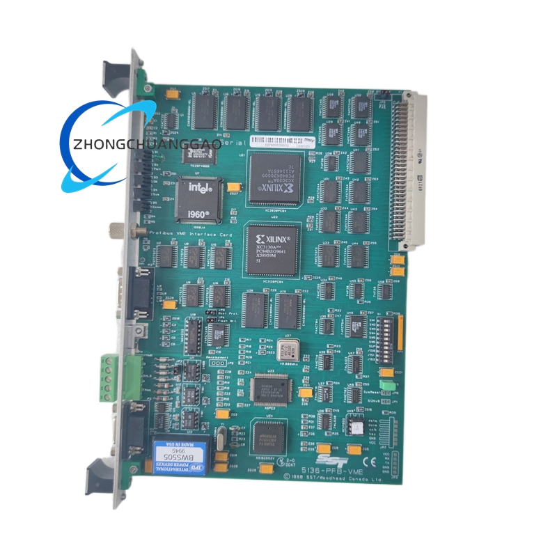
- SST 5136-PFB-VME — 6U VMEbus SBC with PowerPC 750FX (this model)
- SST 5137-PFB-VME — 6U VMEbus SBC with PowerPC 7448 (G4)
- SST 5146-PFB-VME — 6U VMEbus SBC with dual PowerPC 7448
Manufacturer
SST Inc. (Silicon Software Technology)
Cobham plc
Address: 1450 Globe Airport Drive, Suite 400, Anaheim, CA 92807, USA
Parent Company: Cobham plc, Brook Road, Wimborne, Dorset, BH21 2BJ, United Kingdom
Technical Specifications
Functional Features
- PowerPC 750FX processor — delivers 800 MHz clock speed with AltiVec vector processing unit (VMX128) for signal processing and floating-point intensive workloads
- Dual Gigabit Ethernet — supports TCP/IP, UDP, RTP, SNMP, and NTP for spacecraft telemetry, tracking, and command (TT&C) data links
- PCI bus interface — enables expansion with custom I/O boards, FPGA co-processors, or storage controllers
- Dual UART channels — support RS-232, RS-422, and RS-485 protocols for serial command and telemetry interfaces
- 32-bit GPIO bus — provides discrete I/O for relay control, sensor interfacing, and custom logic signaling
- Hardware watchdog timer — automatic system reset on software hang, with configurable timeout from 1 ms to 60 seconds
- ECC-protected DDR SDRAM — single-bit error correction and double-bit error detection on all system memory
- NOR Flash boot storage — non-volatile boot image storage with hardware write-protection for radiation environments
- VME64x support — 64-bit data transfers at 80 MB/s peak bandwidth for high-throughput data acquisition
- Radiation hardening by design (RHBD) — gate-level layout hardening, enclosed-layout transistors (ELT), and triple modular redundancy (TMR) on critical registers
Performance Parameters
Material Composition
Structural Characteristics
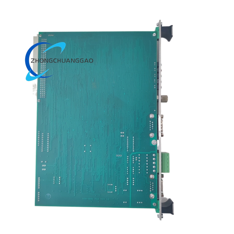
- Form Factor: Full-size 6U VMEbus module, 233.35 mm × 160.02 mm, conforming to ANSI/VITA 1-1997 mechanical standard
- Connector Layout:
- P0/J1 and P0/J2 — 96-pin DIN 41612 VMEbus data and address bus connectors
- P1/J3 — 96-pin DIN 41612 power supply connector (VMEbus power)
- P2/J4 and P2/J5 — 32-pin DIN 41612 user I/O connectors (GPIO, UART, Ethernet)
- P3/J6 — 32-pin DIN 41612 system management connector (watchdog, reset, interrupt)
- Processor Location: Centrally mounted on the PCB with dedicated heat sink and thermal via array for heat dissipation
- Memory Modules: DDR SDRAM DIMM sockets (SO-DIMM form factor) located adjacent to the processor for minimum trace length
- Ethernet Ports: Two RJ-45 connectors mounted on the rear panel (P2) with integrated magnetic isolation transformers
- PCI Slot: One edge connector on the front panel (P2) for expansion card insertion
- Serial Ports: Two DB-9 connectors on the rear panel (P2) for RS-232/422/485 connectivity
- GPIO Header: Two 40-pin male header connectors on the front panel (P2) for discrete I/O breakout
- Board Thickness: 1.6 mm (standard 6U VME thickness)
Working Principle
- Power-On Reset: Upon application of VMEbus power (+3.3V, +5V, +12V), the on-board power management IC generates all required internal rails (1.2V core, 1.8V I/O, 2.5V DDR, 3.3V aux)
- Boot Sequence: The PowerPC 750FX processor fetches its initial instruction from the on-board NOR Flash at address 0xFFF0 0100 (VMEbus boot vector)
- Memory Initialization: The bootloader configures the DDR SDRAM controller with ECC enabled, performs memory test, and loads the operating system image into RAM
- Peripheral Enumeration: The processor scans the VMEbus for installed modules, initializes the PCI bridge, configures Ethernet controllers (Marvell 88E1111 or equivalent), and enables UART channels
- Application Execution: The operating system (VxWorks, Linux, or LynxOS) schedules tasks across the AltiVec-enabled PowerPC 750FX, utilizing vector units for signal processing and floating-point operations
- I/O Data Flow: Sensor data and command signals enter through UARTs and GPIO, are processed by the CPU, and are transmitted out via Gigabit Ethernet or VMEbus to downstream systems
- Radiation Mitigation: The ECC engine continuously monitors DDR SDRAM for bit flips, correcting single-bit errors and flagging double-bit errors. The watchdog timer monitors software execution and forces a hardware reset if the heartbeat signal is not received within the configured timeout
- Thermal Management: On-board temperature sensors feed data to the processor’s thermal management unit, which throttles clock speed if junction temperature exceeds 105°C
Advantages and Highlights
- Radiation-hardened PowerPC 750FX at 800 MHz — one of the highest-performance radiation-tolerant processors available in VME form factor
- AltiVec VMX128 vector unit — delivers 2× to 4× performance improvement over scalar PowerPC for DSP and image processing workloads
- Dual Gigabit Ethernet — enables redundant high-bandwidth data links for spacecraft TT&C without additional interface cards
- ECC-protected DDR SDRAM up to 2 GB — provides large memory footprint for complex real-time operating systems and data buffering
- MIL-STD-1553B option — bus controller module available for direct integration with MIL-STD-1553 avionics data buses
- ESCC QML Class Q certified — European Space Component Coordination qualified manufacturing list, accepted by ESA and major European space agencies
- Extended temperature range -40°C to +85°C — fully operational across the complete military and space thermal envelope
- Long lifecycle availability — SST/Cobham guarantees minimum 15-year product lifecycle for space and defense programs
- DO-254 ready — FPGA-based variants available for DO-254 Design Assurance Level A applications
Applicable Industries
Installation Requirements
- Installation must be performed by qualified personnel trained in VMEbus systems and ESD precautions
- The board must be inserted into a VMEbus chassis with verified +3.3V, +5V, and +12V power rail stability (ripple < 50 mV peak-to-peak)
- Do not exceed the maximum current draw of 5 A on the +3.3V rail and 3 A on the +5V rail from the VMEbackplane
- The board must be secured with two captive screws at the front panel mounting points to prevent vibration-induced connector disengagement
- Ensure proper airflow across the processor heatsink — minimum 100 LFM (linear feet per minute) across the board surface
- Connect all P0, P1, P2, and P3 connectors fully before applying power — partial insertion causes bus contention and permanent damage
- Ground the chassis to the system earth ground before inserting the board
- Configure the VMEbus address switches (if applicable) to a unique address not conflicting with other modules in the crate
- After installation, perform a full VMEbus scan using the operating system’s VME enumeration tools to verify all peripherals are detected
Usage Precautions
- Do not insert or remove the board while the VMEbus is powered — hot-plugging is not supported and causes electrical damage to connectors and bus transceivers
- Do not exceed the operating temperature of +85°C — the processor will throttle at 105°C and latch up at 125°C, causing permanent damage
- Do not apply voltage to any I/O connector before the board is fully seated and powered — unpowered I/O pins cause latch-up in the I/O buffer ICs
- Do not use non-ESCC-qualified replacement components — all parts must meet QML Class Q or equivalent qualification for radiation-tolerant applications
- Do not disable the ECC function in DDR SDRAM — operating without ECC in a radiation environment causes uncorrectable memory errors
- Do not connect Ethernet cables to a live network without proper grounding — the magnetic isolation transformers provide 1.5 kV isolation, but external ESD events exceeding 8 kV damage the PHY
- Do not modify the board firmware without re-qualifying for radiation tolerance — software changes can alter the radiation response of the system
- Do not store the board in environments with relative humidity exceeding 95% — moisture ingress degrades solder joints and conformal coating adhesion
- Recalibrate the system after any physical shock exceeding 50 g — mechanical shock can shift oscillator frequencies and degrade timing accuracy
- Replace the board at end of lifecycle (15 years from manufacture date) — component obsolescence and radiation degradation accumulate over time
Part Number Decoding
Document Reference
- Manufacturer: SST Inc. (Silicon Software Technology), 1450 Globe Airport Drive, Suite 400, Anaheim, CA 92807, USA
- Parent Company: Cobham plc, Brook Road, Wimborne, Dorset, BH21 2BJ, United Kingdom
- ESCC QML Listing: Available under ESCC QML Class Q, QML Number: 3420-001 (verify current listing)
- Applicable Standards: MIL-STD-1553B, MIL-STD-750, MIL-STD-883, DO-160G, DO-254, ANSI/VITA 1-1997
- Operating Systems Supported: VxWorks 5.5/6.x, VxWorks 7, LynxOS-178, pSOS+, Linux 2.4/2.6 (MontaVista, Wind River)
- Processor Family: Freescale (NXP) PowerPC 750FX, QorIQ P1012NSE2DFB (cross-reference)
- Ethernet PHY: Marvell 88E1111 or equivalent, 10/100/1000 Mbps
- PCI Bridge: Tundra (IDT) Tsi148 or equivalent
Reviews
There are no reviews yet.