Product Short Description
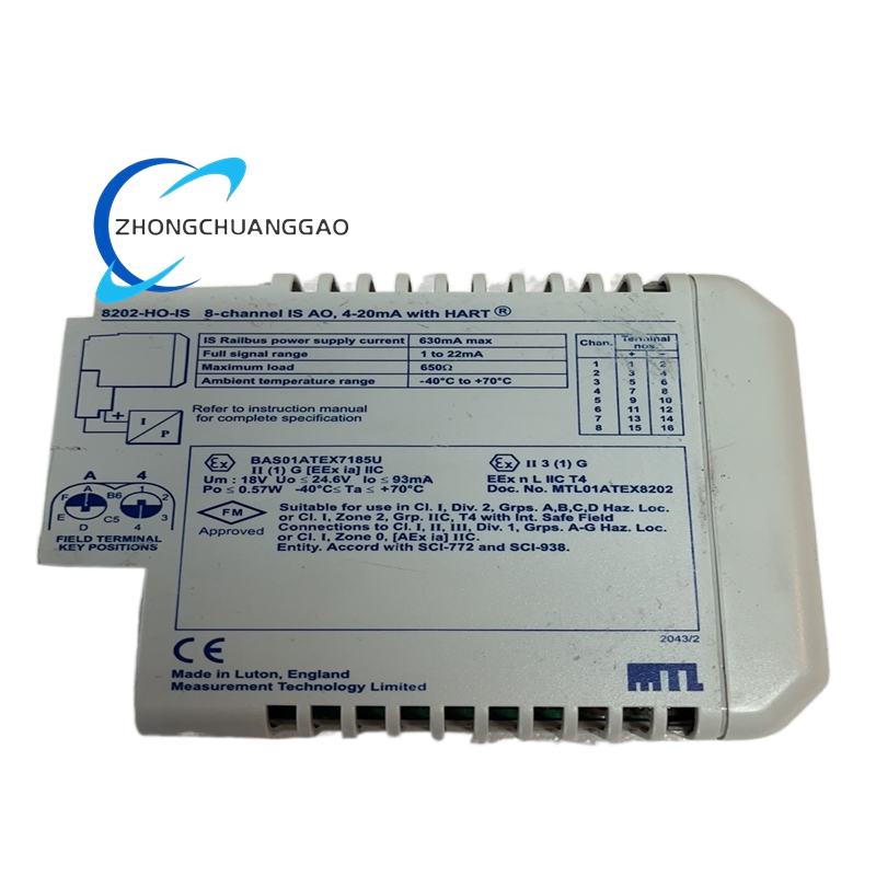
The MTL 8202-HO-IS is a hermetically sealed intrinsically safe (IS) barrier designed to provide galvanic isolation and energy limitation for signals entering hazardous (classified) areas in explosive atmospheres. It is part of the MTL 8200 Series of isolators and barriers, widely deployed in process industries, oil and gas, chemical plants, refineries, and pharmaceutical facilities where explosive gas or dust atmospheres exist.
Description
Model Series
| Model | Series | Key Variant |
|---|---|---|
| 8202-HO-IS | MTL 8200 Series | Hermetically sealed, High Output, Intrinsically Safe, Isolated |
| 8201-LO-IS | MTL 8200 Series | Hermetically sealed, Low Output, Intrinsically Safe, Isolated |
| 8202-LO-IS | MTL 8200 Series | Hermetically sealed, Low Output, Intrinsically Safe, Isolated |
| 8202-HO | MTL 8200 Series | Hermetically sealed, High Output, Non-IS (safe area only) |
| 8201-LO | MTL 8200 Series | Hermetically sealed, Low Output, Non-IS (safe area only) |
| 8232-NAMUR | MTL 8200 Series | Hermetically sealed, NAMUR interface, Intrinsically Safe |
| 8200-IS | MTL 8200 Series | Standard (non-hermetic), Intrinsically Safe, Isolated |
| 8242-IS | MTL 8200 Series | 4-channel, Hermetically sealed, Intrinsically Safe |
| 8244-IS | MTL 8200 Series | 4-channel, Hermetically sealed, High Output, Intrinsically Safe |
| 5516-IS | MTL 5500 Series | Non-isolated, Intrinsically Safe, Zener barrier |
| 5524-IS | MTL 5500 Series | 4-channel, Non-isolated, Intrinsically Safe |
Technical Specifications
| Parameter | Value |
|---|---|
| Barrier Type | Hermetically Sealed Intrinsically Safe Isolator |
| Isolation Type | Galvanic Isolation (magnetic coupling) |
| Output Configuration | High Output (HO) — up to 100 mA per channel |
| Number of Channels | 2 channels (dual-channel barrier) |
| Input Signal Type | 4–20 mA, 0–20 mA, 0–10 VDC, 1–5 VDC (configurable) |
| Output Signal Type | 4–20 mA (passive), 0–20 mA, 0–10 VDC (active) |
| Supply Voltage (Safe Area) | 24 VDC nominal (18 VDC to 30 VDC range) |
| Output Current (HO Variant) | Up to 100 mA per channel (continuous) |
| Output Current (LO Variant) | Up to 20 mA per channel (continuous) |
| Intrinsic Safety Certification | ATEX, IECEx, FM, CSA, TIIS |
| Gas Group Classification | IIA, IIB, IIC (T1 to T6) |
| Dust Group Classification | IIIA, IIIB, IIIC (T135°C to T85°C) |
| Zone Rating (Gas) | Zone 0, Zone 1, Zone 2 |
| Zone Rating (Dust) | Zone 20, Zone 21, Zone 22 |
| Temperature Class | T1 to T6 (gas), T85°C to T135°C (dust) |
| Enclosure Rating | IP65 (front panel), IP20 (rear terminals) |
| Operating Temperature | -20°C to +60°C (-4°F to +140°F) |
| Storage Temperature | -40°C to +85°C (-40°F to +185°F) |
| Supply Voltage (Hazardous Area) | Limited to Uo ≤ 30 VDC, Io ≤ 100 mA (HO variant) |
| Maximum Cable Capacitance | 200 nF (per channel) |
| Maximum Cable Inductance | 10 mH (per channel) |
| Response Time | <10 ms (typical) |
| Isolation Voltage | 1500 VAC RMS (50 Hz, 1 minute) between input and output |
| Insulation Resistance | >100 MΩ at 500 VDC (between channels, between channels and ground) |
| Dimensions (Approx.) | 120 mm × 90 mm × 65 mm (W × H × D) |
| Weight (Approx.) | 0.45 kg (1.0 lb) |
| Mounting | 35 mm DIN rail (EN 60715) or panel mount |
| Certifications | ATEX II 1/2 G Ex ia IIC T6, IECEx, FM Class I Div 1 Gr A-D, CSA Class I Div 1 Gr A-D, TIIS |
| Approvals | SIL 2 capable (per IEC 61508) |
Functional Features
- Hermetically sealed construction — all internal components are enclosed in a welded metal can, providing immunity to humidity, dust, and chemical contamination; ensures long-term calibration stability
- Galvanic isolation via magnetic coupling — input and output circuits are completely isolated using transformer coupling, eliminating ground loops and providing noise immunity
- High output current (100 mA per channel) — capable of powering multiple field instruments (transmitters, valves, solenoids) from a single barrier channel without external power supplies in the hazardous area
- Dual-channel configuration — two independent barrier channels in a single housing, reducing panel space and wiring complexity
- Intrinsic safety certification for IIC gas group — approved for the most hazardous atmospheres including hydrogen and acetylene (T6 temperature class)
- Configurable input/output signal types — supports 4–20 mA, 0–20 mA, 0–10 VDC, and 1–5 VDC signals via internal DIP switches or jumpers
- Active and passive output modes — active output provides powered signal to field instruments; passive output allows loop-powered 4–20 mA transmitters
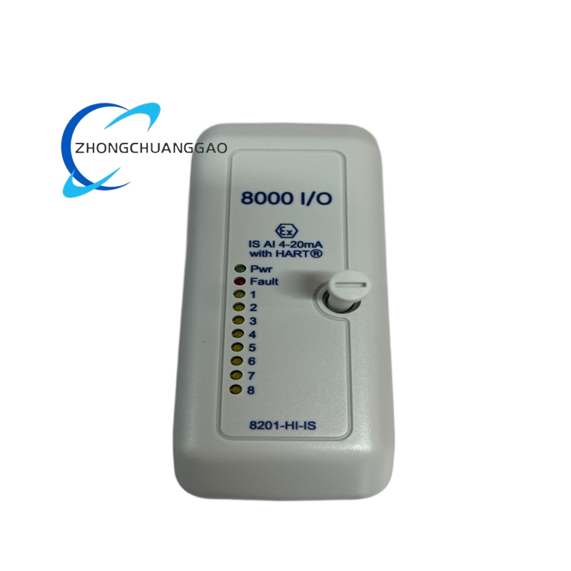
- Built-in diagnostic LEDs — per-channel power, fault, and signal status indicators for rapid troubleshooting
- Fail-safe design — in the event of internal failure, the barrier limits energy to the hazardous area to below ignition levels (intrinsically safe by design)
- Wide supply voltage range (18–30 VDC) — accommodates most standard 24 VDC control system power supplies without adjustment
- Low power consumption — typical consumption <2 W per channel, minimizing heat generation in the control panel
- DIN rail or panel mount — flexible installation options for control cabinets and marshalling panels
Performance Parameters
| Parameter | Specification |
|---|---|
| Output Current (HO) | Up to 100 mA per channel (continuous) |
| Output Current (LO) | Up to 20 mA per channel (continuous) |
| Voltage Drop (Output) | <2.5 VDC at 100 mA (HO mode) |
| Voltage Drop (Output) | <1.0 VDC at 20 mA (LO mode) |
| Isolation Resistance | >100 MΩ at 500 VDC (between channels, channels to ground) |
| Dielectric Strength | 1500 VAC RMS for 1 minute (input to output, channels to ground) |
| Response Time | <10 ms (typical, 4–20 mA signal) |
| Linearity Error | <0.1% of full scale |
| Temperature Drift | <0.01% per °C (after warm-up) |
| Supply Voltage Effect | <0.1% output change per 10% input voltage variation |
| Load Effect | <0.1% output change from no-load to full-load |
| Common Mode Rejection | >80 dB (at 50 Hz) |
| MTBF (Mean Time Between Failures) | >200,000 hours (at 25°C ambient) |
| SIL Capability | SIL 2 per IEC 61508 (with proof test interval) |
| Cable Capacitance Limit | 200 nF per channel (external cable) |
| Cable Inductance Limit | 10 mH per channel (external cable) |
Material Composition
| Component | Material |
|---|---|
| Enclosure / Housing | Aluminum alloy (AL6061-T6), anodized, epoxy powder-coated (RAL 7032 gray) |
| Hermetic Seal Can | Kovar alloy (FeNiCo), laser-welded hermetic seal |
| Internal Transformer Core | Nickel-iron alloy (Mu-metal), high-permeability |
| Printed Circuit Board (PCB) | FR-4 glass epoxy, conformal coated with acrylic coating |
| Terminal Blocks | Phosphor bronze, tin-plated, screw-clamp type, rated 10 A |
| Connector Pins | Gold-plated brass |
| Mounting Bracket / DIN Rail Clip | Galvanized steel, powder-coated |
| LED Indicators | High-brightness epoxy-encapsulated LEDs (red, green, yellow) |
| Internal Wiring | Tinned copper, 22 AWG minimum, silicone-insulated, 200°C rated |
| Heat Sink (Internal) | Extruded aluminum, anodized black |
| Gaskets / Seals (Front Panel) | Silicone rubber (VMQ), 70 Shore A hardness, IP65 rated |
| Surge Protection Devices | TVS diodes and metal-oxide varistors (MOVs) on all external I/O |
| Internal Potting Compound | Epoxy resin, hermetically sealed over all critical components |
Structural Features
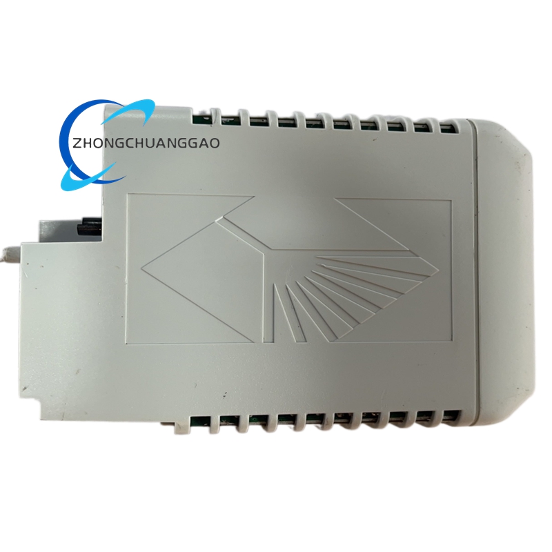
- Compact DIN-rail mountable module designed for installation inside control cabinets, marshalling panels, or junction boxes
- Front panel with LED indicators: Power (green), Channel 1 Fault (red), Channel 2 Fault (red), Signal Active (green)
- Front-panel DIP switches for configuring input/output signal type (4–20 mA, 0–20 mA, 0–10 VDC, 1–5 VDC)
- Rear terminal block array with clearly labeled connections for:
- Safe area input (24 VDC supply and signal in)
- Hazardous area output (signal out to field instruments)
- Ground connection (chassis ground and IS ground)
- Hermetically sealed internal can — all magnetic coupling transformers, circuitry, and connections are enclosed in a laser-welded Kovar can, preventing any moisture or contaminant ingress
- Ventilation slots on top and bottom for natural convection cooling (no fan required)
- Surge protection devices (TVS diodes and MOVs) on all external connections
- EMC shielding via metal enclosure and filtered I/O connections
- IP65 front panel rating — protected against water jets and dust ingress from the front
- IP20 rear rating — rear terminals require enclosure protection
- Tamper-resistant terminal cover — hinged cover with gasket protects terminals from dust and accidental contact
- Label area — laser-etched identification on the enclosure face (model number, ratings, certifications)
Working Principle
- The barrier receives a safe-area input signal (4–20 mA, 0–20 mA, 0–10 VDC, or 1–5 VDC) from the control system (DCS, PLC, or transmitter)
- The input signal drives an oscillator circuit that generates a high-frequency AC signal (typically 50–100 kHz)
- The AC signal is coupled across the isolation barrier via a magnetic transformer (galvanic isolation) — there is no electrical connection between input and output; energy is transferred via magnetic field
- On the hazardous area output side, the AC signal is rectified and filtered to recreate the original DC signal (4–20 mA or voltage)
- The output circuit includes energy-limiting components (resistors, zener diodes, fuses) that restrict the maximum voltage (Uo ≤ 30 VDC) and current (Io ≤ 100 mA for HO variant) to levels below the ignition threshold of the surrounding explosive atmosphere
- The hermetic seal ensures that the internal components remain protected from humidity, dust, and chemical contamination, maintaining long-term calibration accuracy
- The intrinsic safety principle guarantees that even under fault conditions (short circuit, open circuit, component failure), the energy delivered to the hazardous area remains below the minimum ignition energy (MIE) of the gas or dust present
- The dual-channel design provides two independent isolated barriers in a single housing, each with its own input, output, and energy-limiting circuit
Advantages and Highlights
- Hermetically sealed construction — superior long-term stability compared to non-hermetic barriers; immune to humidity, dust, and chemical contamination
- High output current (100 mA per channel) — powers multiple field instruments from a single channel; eliminates need for local power supplies in hazardous areas
- Galvanic isolation — eliminates ground loops, provides noise immunity, and allows different ground potentials between safe and hazardous areas
- Intrinsic safety certified for IIC T6 — approved for the most hazardous gas atmospheres including hydrogen and acetylene
- Dual-channel in single housing — reduces panel space, wiring, and cost by 50% compared to two single-channel barriers
- Configurable signal types — supports 4–20 mA, 0–20 mA, 0–10 VDC, and 1–5 VDC via DIP switches
- Fail-safe by design — internal failure automatically limits energy to safe levels; no risk of ignition
- SIL 2 capable — meets IEC 61508 functional safety requirements for safety instrumented systems
- Wide supply voltage range (18–30 VDC) — compatible with most 24 VDC control systems
- Built-in diagnostics — per-channel LED indicators for power, fault, and signal status
- Low power consumption (<2 W per channel) — minimal heat generation in control panels
- ATEX, IECEx, FM, CSA, TIIS certified — globally approved for hazardous area use
- Long service life — hermetic seal prevents component degradation; MTBF >200,000 hours
- Compact form factor — fits in tight spaces on DIN rails and in control cabinets
Applicable Industries
| Industry | Application |
|---|---|
| Oil and Gas (Upstream) | Wellhead monitoring, pipeline SCADA, gas detection, valve control in Zone 0/1 areas |
| Oil and Gas (Downstream) | Refinery process control, tank farm monitoring, loading rack instrumentation in Zone 1/2 areas |
| Chemical Processing | Reactor temperature/pressure monitoring, solvent level detection, valve actuation in hazardous areas |
| Pharmaceutical Manufacturing | Solvent recovery monitoring, reactor control, cleanroom-adjacent hazardous area instrumentation |
| Petrochemical | Ethylene/propylene plant instrumentation, flare system monitoring, compressor control |
| Mining | Methane gas detection, conveyor monitoring, ventilation control in underground hazardous areas |
| Power Generation | Hydrogen-cooled generator monitoring, coal dust detection, boiler control in classified areas |
| Water and Wastewater | Hydrogen sulfide (H2S) gas detection, chlorine monitoring, sludge digester control |
| Food and Beverage | Alcohol vapor detection, solvent-based cleaning monitoring, dust explosion prevention |
| Pulp and Paper | Turpentine vapor detection, kiln gas monitoring, dust collector control |
| Marine and Offshore | Gas detection on FPSO/FSO, cargo tank monitoring, engine room instrumentation |
| Paint and Coating | Solvent vapor monitoring, spray booth control, dust collector instrumentation |
| Agriculture | Grain dust explosion prevention, biogas monitoring, silo level detection |
Installation Requirements
| Requirement | Specification |
|---|---|
| Mounting | 35 mm standard DIN rail (EN 60715) or panel mount with 4 × M4 screws |
| Ambient Temperature | -20°C to +60°C (-4°F to +140°F) |
| Relative Humidity | 5% to 95% non-condensing (IP65 front rated for wet conditions) |
| Altitude | Up to 2,000 m (6,562 ft) above sea level (derate above 1,000 m) |
| Vibration | <5 g RMS (10–500 Hz), per IEC 60068-2-6 |
| Shock | <50 g, 11 ms half-sine, per IEC 60068-2-27 |
| Enclosure IP Rating | IP65 (front panel), IP20 (rear terminals — install in NEMA 1 or higher enclosure) |
| Clearance | Minimum 50 mm above and below for ventilation; 25 mm on sides |
| Cable Sizing (Safe Area Input) | Minimum 0.75 mm² (18 AWG) copper for signal and power |
| Cable Sizing (Hazardous Area Output) | Minimum 0.75 mm² (18 AWG) copper, intrinsically safe rated cable required |
| Cable Type (Hazardous Area) | IS-rated cable with maximum 200 nF capacitance and 10 mH inductance per channel |
| Grounding | Chassis ground required; connect to control cabinet ground bus with minimum 2.5 mm² (14 AWG) copper |
| IS Ground Connection | Dedicated IS ground bar required; do not share with power ground |
| Torque on Terminal Screws | 0.8 Nm (7 in-lb) maximum; do not overtighten |
| Torque on Mounting Bolts | 2.5 Nm (22 in-lb) maximum |
| EMI Environment | Install away from high-current switching devices; maintain 100 mm separation from VFDs and soft starters |
| Cable Routing | Separate IS cables from power cables by minimum 100 mm; use dedicated cable trays |
| Fuse Protection (Safe Area) | Recommended: 500 mA fast-blow fuse per channel on safe-area input |
Usage Precautions
- Never connect the barrier to a live circuit without verifying all wiring against the wiring diagram — incorrect connections will destroy the barrier and compromise intrinsic safety
- Verify cable capacitance and inductance before commissioning — total cable capacitance must not exceed 200 nF per channel; total inductance must not exceed 10 mH per channel
- Use only intrinsically safe rated cable for hazardous area connections — standard cable does not meet IS requirements and will void certification
- Do not exceed the rated output current of 100 mA per channel (HO variant) — overloading will destroy the energy-limiting components and compromise safety
- Do not bypass the built-in surge protection devices — external transients from lightning or switching will damage internal circuitry
- Allow 30 seconds warm-up time after initial power-on before expecting accurate signal transmission
- Do not adjust internal components unless qualified — incorrect settings cause calibration drift and loss of intrinsic safety certification
- Use shielded cable for all signal wiring in electrically noisy environments — unshielded cables near VFDs or welders cause false readings
- Ensure proper ventilation — do not install in a sealed enclosure without airflow; overheating above 60°C causes thermal shutdown
- Perform annual inspection of all terminal connections for tightness, corrosion, and wire insulation integrity
- Do not operate the barrier with the front cover removed — exposed terminals carry up to 30 VDC and 100 mA
- When replacing the unit, match the model number exactly — 8202-HO-IS is not interchangeable with 8201-LO-IS without reconfiguration
- Log all fault events using the built-in LED indicators or external SCADA for preventive maintenance
- Do not use the barrier with supply voltages exceeding 30 VDC — dielectric breakdown will occur and intrinsic safety will be lost
- For multi-channel operation, ensure each channel is independently fused on the safe-area side
- Do not mix IS cables with non-IS cables in the same tray — this creates a risk of energy transfer to non-IS equipment
- Store spare units in a dry, temperature-controlled environment (0°C to 40°C, <70% RH) with anti-static packaging
- Update firmware (if applicable) via MTL configuration software to the latest version for improved algorithms and bug fixes
- Do not modify the internal firmware or circuitry — only MTL-authorized personnel should perform modifications
Software and Configuration Tools
| Tool | Function |
|---|---|
| MTL Configurator Software | PC-based configuration via USB or RS-485; adjust signal type, scaling, and diagnostic thresholds |
| MTL Smart Adapter | Handheld configuration tool for field setup and calibration verification |
| Modbus RTU Register Map | Standard register map for third-party SCADA and DCS integration |
| HART Compatibility | Supports HART communication on 4–20 mA channels for smart transmitter configuration |
Key Parameters Summary (Bold Reference)
| Field | Value |
|---|---|
| Product Name | MTL 8202-HO-IS Hermetically Sealed Intrinsically Safe Barrier |
| Barrier Type | Hermetically Sealed, Galvanically Isolated, Intrinsically Safe |
| Output Configuration | High Output (HO) — up to 100 mA per channel |
| Number of Channels | 2 channels (dual-channel) |
| Input Signal | 4–20 mA, 0–20 mA, 0–10 VDC, 1–5 VDC (configurable) |
| Output Signal | 4–20 mA (passive/active), 0–20 mA, 0–10 VDC (active) |
| Supply Voltage | 24 VDC (18–30 VDC range) |
| Gas Group | IIA, IIB, IIC (T1 to T6) |
| Dust Group | IIIA, IIIB, IIIC (T85°C to T135°C) |
| Zone Rating (Gas) | Zone 0, Zone 1, Zone 2 |
| Zone Rating (Dust) | Zone 20, Zone 21, Zone 22 |
| Isolation Voltage | 1500 VAC RMS (50 Hz, 1 minute) |
| Output Current (HO) | Up to 100 mA per channel (continuous) |
| Voltage Drop (HO) | <2.5 VDC at 100 mA |
| Cable Capacitance Limit | 200 nF per channel |
| Cable Inductance Limit | 10 mH per channel |
| Enclosure Rating | IP65 (front), IP20 (rear) |
| Operating Temperature | -20°C to +60°C |
| Certifications | ATEX II 1/2 G Ex ia IIC T6, IECEx, FM Class I Div 1 Gr A-D, CSA Class I Div 1 Gr A-D, TIIS, SIL 2 |
| Mounting | 35 mm DIN rail or panel mount |
| Weight | 0.45 kg (1.0 lb) |
| Dimensions (Approx.) | 120 mm × 90 mm × 65 mm |
Reviews
There are no reviews yet.