Product Short Description
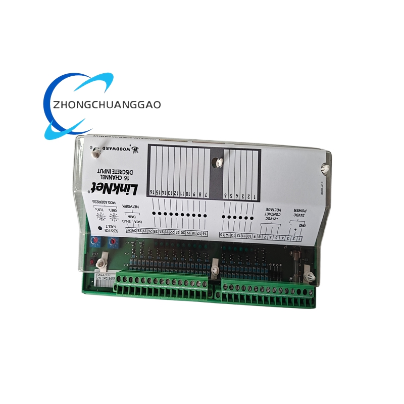
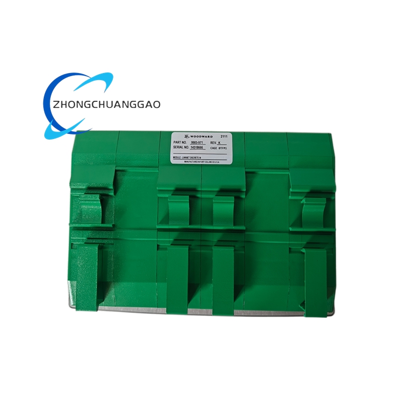
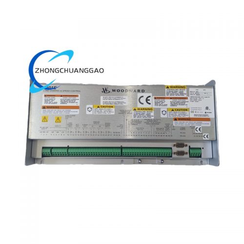
The Woodward 9905-971 is a fully digital, microprocessor-based engine speed and load governor designed for diesel and gas engine applications. It provides precise engine speed regulation, load sharing, fuel limiting, and comprehensive engine protection in a compact DIN-rail-mountable package. The unit replaces legacy mechanical and analog electronic governors with a fully programmable digital control platform. It interfaces with Woodward EasYgen, 505E, and third-party engine controllers via CAN bus or analog signals and drives Woodward 9907-series magnetic fuel actuators directly.
Description
Product Category
Digital Engine Governor / Speed Controller / Load Sharing Controller / Actuator Driver
Key Functions
- Engine Speed Control — Maintains setpoint speed under varying load conditions with digital PID regulation
- Isochronous Speed Control — Holds exact setpoint speed (0% droop) for single-generator or grid-connected applications
- Droop Speed Control — Programmable droop from 1% to 10% for parallel generator load sharing
- Load Sharing — Distributes real power (kW) equally among parallel generators using droop characteristic
- Fuel Limiting — Restricts maximum fuel delivery to prevent engine overload and protect turbocharger
- Starting Control — Manages crank and run fuel quantities during engine start sequences
- Overspeed Protection — Automatic fuel shutoff on engine overspeed with configurable trip point and delay
- Underspeed Protection — Alarm and shutdown on low engine speed
- Reverse Power Protection — Detects reverse power flow (motoring) and alarms or trips
- Governor Alarm Outputs — Provides relay contacts for alarm and shutdown signaling
- Local/Remote Mode Selection — Supports both local manual override and remote automatic control
- Fail-Safe Positioning — Drives actuator to safe position (fuel cut or full fuel) on signal loss
Technical Specifications
| Parameter | Value |
|---|---|
| Supply Voltage | 24 VDC nominal (range: 18 VDC to 32 VDC) |
| Power Consumption | Less than 6 W typical, 8 W maximum |
| Operating Temperature | -40°C to +85°C (-40°F to +185°F) |
| Storage Temperature | -55°C to +125°C (-67°F to +257°F) |
| Humidity Rating | 5% to 95% non-condensing |
| Vibration Rating | IEC 60068-2-6 compliant (5 g RMS, 10–2000 Hz) |
| Altitude Rating | Up to 10,000 ft (3,048 m) without derating |
| EMC Compliance | IEC 61000-6-2 (Industrial Environment) |
| Enclosure Protection | IP20 (when mounted in enclosure), conformally coated PCB |
| Weight | Approximately 0.45 kg (1.0 lbs) |
| Dimensions (L x W x H) | Approximately 130 mm x 90 mm x 55 mm |
| DIN Rail Mounting | 35 mm top-hat rail (EN 60715) |
Actuator Output Specifications
| Parameter | Value |
|---|---|
| Maximum Drive Current | 8 A continuous |
| Peak Drive Current | 12 A for 5 seconds maximum |
| PWM Frequency | 125 Hz (fixed) |
| PWM Duty Cycle Range | 0% to 100% |
| Position Resolution | 10-bit (1,024 steps) |
| Position Accuracy | ±0.5% of full stroke |
| Response Time (0% to 100%) | Less than 100 ms |
| Actuator Compatibility | Woodward 9907-167, 9907-168, 9930-823, 9907-046 magnetic actuators |
Communication Interfaces
| Interface | Protocol |
|---|---|
| CAN Bus (Primary) | Woodward CAN 2.0B, 500 kbps |
| Analog Input (Speed Setpoint) | 4 mA to 20 mA or 0 VDC to 5 VDC |
| Analog Input (Load Reference) | 4 mA to 20 mA or 0 VDC to 5 VDC |
| Analog Output (Speed Indication) | 4 mA to 20 mA (configurable) |
| Analog Output (Load Indication) | 4 mA to 20 mA (configurable) |
| Discrete Inputs | 6 dry contact inputs (enable, mode select, alarm reset, ESD, etc.) |
| Discrete Outputs | 3 relay outputs (alarm, fault, status) |
| Serial Port | RS-485, Modbus RTU (for configuration and diagnostics) |
| Speed Sensor Input | Magnetic pickup (MPU) or variable reluctance sensor, 0 Hz to 2000 Hz |
Protection Features
- Overspeed Trip — Configurable trip point 102% to 115% of setpoint, adjustable delay 0 to 30 seconds
- Underspeed Trip — Configurable trip point 85% to 98% of setpoint, adjustable delay 0 to 30 seconds
- ESD Actuation — Fuel cutoff within 100 ms of ESD signal activation
- Actuator Coil Open Circuit Detection — Immediate fault alarm, actuator drives to safe position
- Actuator Coil Short Circuit Detection — Immediate fault alarm, output current limited to 2 A
- Position Sensor Failure Detection — Loss of feedback triggers safe shutdown
- Overtemperature Protection — Internal thermal shutdown at +105°C junction temperature
- Supply Voltage Monitor — Low voltage alarm at <18 VDC, high voltage alarm at >32 VDC
- CAN Bus Timeout — Actuator drives to safe position within 200 ms of CAN communication loss
- Reverse Polarity Protection — Internal fuse blows on reverse polarity connection (fuse rating: 2 A fast-blow)
Control Modes
| Mode | Description |
|---|---|
| Isochronous Mode | Actuator follows speed setpoint with 0% droop — single generator or grid-connected |
| Droop Mode | Actuator follows speed setpoint with 1% to 10% droop — parallel generator load sharing |
| CAN Command Mode | Actuator follows digital position commands from EasYgen or EGC-4 via CAN bus (primary mode) |
| Analog Command Mode | Actuator follows analog signal (4–20 mA or 0–5 VDC) from external controller (backup mode) |
| Local Manual Mode | Local potentiometer override for commissioning, testing, and maintenance |
| Fail-Safe Mode | Actuator drives to full closed (fuel cut) or full open on signal loss (configurable via DIP switch) |
Material Composition
| Component | Material |
|---|---|
| Housing | Die-cast aluminum alloy with powder-coat finish (RAL 7035 light gray) |
| Front Cover | Polycarbonate with UV-resistant coating and membrane keypad overlay |
| PCB | FR-4 fiberglass epoxy, conformally coated with silicone |
| Connectors | Phoenix Contact screw terminal blocks, tin-plated brass |
| Terminal Blocks | Phoenix Contact PT series, tin-plated brass |
| Mounting Bracket | Stainless steel 304 with vibration-damping rubber grommets |
| Gaskets/Seals | Silicone rubber grommets for DIN rail mounting |
| Potentiometer | Cermet (ceramic-metal) trim potentiometer for local override |
| LEDs | High-brightness LEDs rated for 100,000 hours operation |
| Fuse | 2 A fast-blow fuse for reverse polarity protection |
Structural Features
- DIN rail mountable on 35 mm top-hat rail (EN 60715)
- Front-accessible terminal blocks for all wiring connections
- Membrane keypad with 2-line LCD display for local configuration
- 3 LED status indicators: Power (green), Run (green), Alarm (amber)
- DIP switches on PCB for mode selection and fail-safe configuration
- Conformal-coated PCB for moisture, dust, and chemical resistance
- Integrated EMC filter on power and signal inputs
- Compact footprint — fits in standard DIN rail enclosures
Working Principle
The 9905-971 receives a frequency signal from a magnetic pickup sensor mounted on the engine flywheel or gear. The internal 16-bit microcontroller converts the frequency to engine RPM and compares it to the setpoint speed. The error signal is processed through a PID (Proportional-Integral-Derivative) control algorithm with feed-forward compensation. The controller outputs a 125 Hz PWM signal to the fuel actuator, adjusting fuel rack position to minimize the speed error. For load sharing, the controller adjusts the speed setpoint based on the load reference input, creating a controlled droop characteristic. All position data, diagnostic status, and alarm conditions are transmitted back to the engine controller via CAN bus in real time at 500 kbps.
Advantages and Highlights
- Fully Digital Architecture — No mechanical linkages, no wear parts in the controller
- High Precision — Speed regulation within ±0.1% of setpoint
- Fast Response — <100 ms transient response
- Remote Configuration — Full parameter set via CAN bus or Modbus RTU
- Wide Input Compatibility — Supports MPU, variable reluctance, and Hall-effect speed sensors
- Redundant Protection — Multiple independent overspeed and underspeed protection channels
- Compact Footprint — 130 mm x 90 mm x 55 mm, fits in standard DIN rail enclosures
- Long Service Life — No mechanical fatigue, MTBF exceeds 50,000 hours
- Dual Input Redundancy — CAN bus and analog input provide command redundancy
- Fail-Safe Operation — Drives actuator to safe position on loss of speed signal or CAN communication
Applicable Industries
- Power Generation — Diesel and gas generator sets (standby, prime, continuous)
- Marine Propulsion — Auxiliary and main engine governors
- Oil and Gas — Compressor drivers, pump drivers, wellhead power units
- Mining — Diesel generator sets for underground and surface operations
- Rail — Auxiliary power units (APUs)
- Industrial — Any diesel/gas engine requiring electronic speed control
- Telecommunications — Backup power generator sets
- Data Centers — Standby and prime power generation
Compatible Engine Controllers
| Controller | Communication |
|---|---|
| EasYgen 3000 / 3500 / 4000 | CAN bus (primary) |
| EGC-4 | CAN bus (primary) |
| 505E / 505D | Analog 4–20 mA (backup) |
| EASYgen-3200 | CAN bus |
| Woodward 8440 Load Share Controller | CAN bus |
Compatible Actuator Models (Woodward)
| Actuator Model | Type | Voltage | Force |
|---|---|---|---|
| 9907-167 | Magnetic, high-force | 24 VDC | 800 N |
| 9907-168 | Magnetic, standard-force | 12/24 VDC | 500 N |
| 9930-823 | Magnetic, high-force | 24 VDC | 1000 N |
| 9907-046 | Magnetic, low-force | 24 VDC | 200 N |
| 9907-771 | Electronic, 4–20 mA input | 24 VDC | 600 N |
| 9907-773 | Electronic, 0–10 VDC input | 24 VDC | 600 N |
Model Series Cross-Reference
| Model | Key Difference from 9905-971 |
|---|---|
| 9905-951 | Basic speed control, no CAN bus, 4 discrete I/O |
| 9905-953 | CAN bus + analog, no ESD input, 4 discrete I/O |
| 9905-971 | Full-featured: CAN bus, analog, ESD, 6 discrete I/O, 10-bit resolution |
| 9905-973 | CAN bus + analog + ESD + 8 discrete I/O, 12-bit resolution |
| 9905-975 | Extended temperature range (-55°C to +105°C), military-grade |
| 9905-979 | Hazardous area rated (ATEX Zone 2, IECEx) |
Certifications and Compliance
| Certification | Standard |
|---|---|
| CE Marking | EN 61010-1, EN 55032 Class A, EN 61000-6-2, EN 61000-6-4 |
| UL Listed | File E147353 (North America) |
| CSA Certified | File LR78161 (Canada) |
| DNV GL Type Approval | For marine installations |
| Lloyd’s Register | Approved for marine generator sets |
| ABS | Approved for marine use |
| ATEX | Standard 9905-971 is NOT rated for hazardous areas; use 9905-979 for ATEX Zone 2 |
| IEC 61508 | SIL 2 capable (when used with SIL-rated engine controller) |
| IEC 61000-6-2 | EMC emission and immunity for industrial environments |
| IEC 60068-2-6 | Vibration resistance |
| RoHS Compliant | EU Directive 2011/65/EU |
| REACH Compliant | EU Regulation 1907/2006 |
Part Number Breakdown
| Segment | Meaning |
|---|---|
| 9905 | Product family — MicroNet Digital Governor |
| 9 | Feature set — Full function with CAN bus, ESD, 6 discrete I/O |
| 71 | Configuration code — Global standard, 24 VDC, 10-bit resolution, DIN rail mount |
Installation Requirements
- Mount on 35 mm DIN rail (EN 60715) or directly on the fuel actuator using the supplied bracket
- Maintain minimum 50 mm clearance on all sides for ventilation
- Route speed sensor cable away from high-current power cables (minimum 150 mm separation)
- Use shielded twisted-pair cable for speed signal (minimum 0.5 mm² cross-section)
- Ground the controller chassis to the engine block ground point using minimum 6 AWG copper wire
- Supply voltage must be 24 VDC regulated with less than 5% ripple
- Torque all terminal connections to 1.2 Nm (10.6 in-lbs)
- Verify speed sensor air gap is within 0.3 mm to 1.5 mm (0.012″ to 0.060″) before startup
- Perform a no-load speed calibration after initial installation
- Do not operate the unit in environments exceeding +85°C ambient temperature
- Verify CAN bus termination resistors (120 Ω) are installed at both ends of the bus
Usage Precautions
- Do not exceed the maximum supply voltage of 32 VDC — permanent damage to internal components will occur
- Do not reverse the polarity of the power supply — internal 2 A fast-blow fuse will open
- Do not operate the unit in environments exceeding +85°C ambient temperature
- Do not expose the PCB to chemical solvents — conformal coating will degrade
- Perform a no-load position calibration after initial installation and after any actuator replacement
- Perform a functional test of all protection relays every 6 months
- Do not modify the firmware using unauthorized tools — this voids the warranty immediately
- The unit contains no user-serviceable components — contact Woodward for all repairs
- Replace the silicone rubber grommets if the DIN rail mounting is compromised
- Verify CAN bus termination resistors (120 Ω) are installed at both ends of the bus at all times
- Do not connect or disconnect the terminal blocks while the unit is powered
- Store the unit in a dry environment with relative humidity below 85%
Warranty
- Standard Warranty: 24 months from date of shipment
- Extended Warranty: Available up to 60 months (Woodward Protect program)
- Warranty Exclusions: Damage caused by reverse polarity, overvoltage, physical impact, unauthorized firmware modification, or operation outside specified environmental limits
Document Reference Numbers
| Document | Number |
|---|---|
| Installation Manual | 9905-IM-001 |
| Operator’s Manual | 9905-OM-001 |
| Configuration Guide | 9905-CG-001 |
| Wiring Diagram | 9905-WD-001 |
| CAN Bus Communication Guide | 9905-CB-001 |
| Diagnostic Procedures | 9905-DP-001 |
| Firmware Update Guide | 9905-FU-001 |
| Actuator Compatibility Chart | 9905-AC-001 |
Reviews
There are no reviews yet.