Product Short Description
Product Overview
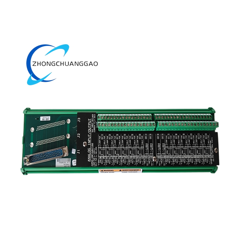
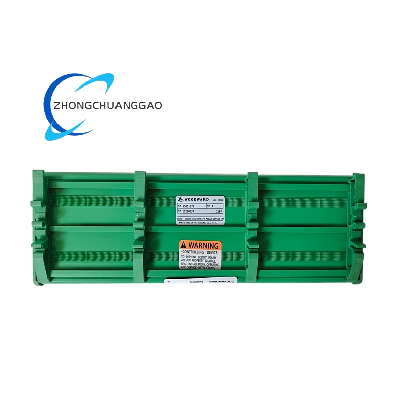
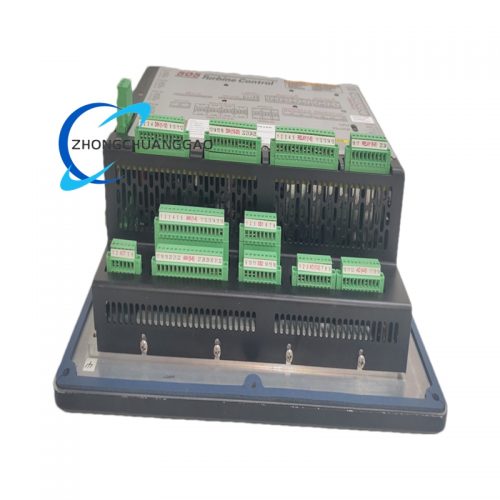
The Woodward 5501-376 is a microprocessor-based digital actuator controller designed for fuel control valve positioning on gas turbine and reciprocating engine generator sets. It interfaces with Woodward EasYgen, EGC-4, and 505E engine controllers to provide precise fuel metering, rapid response actuation, and comprehensive diagnostic feedback. The unit replaces analog servo amplifiers and delivers closed-loop position control with CAN bus communication for seamless integration into modern engine management systems.
Description
Product Category
Fuel Actuator Controller / Servo Amplifier / Valve Positioner for Gas Turbines and Reciprocating Engines
Key Functions
- Fuel Valve Position Control — Drives the fuel control valve to exact commanded positions using closed-loop feedback
- Actuator Position Feedback — Sends real-time valve stroke data back to the engine controller via CAN bus
- Overspeed Protection — Automatic fuel shutoff when engine speed exceeds the configured trip threshold
- Underspeed Protection — Engine alarm and shutdown when speed drops below the minimum setpoint
- Emergency Shutdown (ESD) — Executes immediate fuel cutoff within 50 ms of receiving the ESD signal
- Actuator Health Monitoring — Continuously monitors coil current, position sensor integrity, and internal temperature
- Local Manual Override — Supports local potentiometer control for commissioning and maintenance
- Fail-Safe Actuation — Drives actuator to a pre-configured safe position on loss of command signal or CAN communication
- Valve Stroke Limiting — Configurable minimum and maximum stroke limits to protect the fuel valve
Technical Specifications
| Parameter | Value |
|---|---|
| Supply Voltage | 24 VDC nominal (range: 18 VDC to 32 VDC) |
| Power Consumption | Less than 10 W typical, 15 W maximum |
| Operating Temperature | -40°C to +85°C (-40°F to +185°F) |
| Storage Temperature | -55°C to +125°C (-67°F to +257°F) |
| Humidity Rating | 5% to 95% non-condensing |
| Vibration Rating | IEC 60068-2-6 compliant (5 g RMS, 10–2000 Hz) |
| Altitude Rating | Up to 10,000 ft (3,048 m) without derating |
| EMC Compliance | IEC 61000-6-2 (Industrial Environment, emission and immunity) |
| Enclosure Protection | IP65 when mounted with supplied gasket kit |
| Weight | Approximately 1.4 kg (3.1 lbs) |
| Dimensions (L x W x H) | Approximately 210 mm x 150 mm x 90 mm |
Actuator Drive Specifications
| Parameter | Value |
|---|---|
| Maximum Continuous Drive Current | 12 A |
| Peak Drive Current | 18 A for 5 seconds maximum |
| PWM Frequency | 250 Hz (fixed) |
| PWM Duty Cycle Range | 0% to 100% |
| Position Resolution | 14-bit (16,384 steps) |
| Position Accuracy | ±0.25% of full stroke |
| Response Time (0% to 100%) | Less than 150 ms |
| Position Linearity | ±0.1% of full stroke |
| Deadband | Less than 0.1% of full stroke |
| Actuator Compatibility | Woodward 9907 series, 9930 series magnetic actuators; electronic actuators with 4–20 mA or 0–10 VDC input |
Communication Interfaces
| Interface | Protocol |
|---|---|
| CAN Bus (Primary) | Woodward CAN 2.0B, 500 kbps |
| Analog Input (Position Command) | 4 mA to 20 mA or 0 VDC to 10 VDC |
| Analog Output (Position Feedback) | 4 mA to 20 mA (configurable) |
| Discrete Inputs | 8 dry contact inputs (ESD, enable, mode select, alarm reset, run/stop, etc.) |
| Discrete Outputs | 4 relay outputs (alarm, fault, status, ready) |
| Serial Port | RS-485, Modbus RTU (for configuration, diagnostics, and firmware updates) |
Protection Features
- Overspeed Trip — Configurable trip point, adjustable delay 0 to 30 seconds
- Underspeed Trip — Configurable trip point, adjustable delay 0 to 30 seconds
- ESD Actuation — Fuel cutoff within 50 ms of ESD signal activation
- Actuator Coil Open Circuit Detection — Immediate fault alarm, actuator drives to safe position
- Actuator Coil Short Circuit Detection — Immediate fault alarm, output current limited to 2 A
- Position Sensor Failure Detection — Loss of LVDT or potentiometer feedback triggers safe shutdown
- Overtemperature Protection — Internal thermal shutdown at +110°C junction temperature
- Supply Voltage Monitor — Low voltage alarm at <18 VDC, high voltage alarm at >32 VDC
- CAN Bus Timeout — Actuator drives to safe position within 200 ms of CAN communication loss
- Position Limit Monitoring — Alarm and shutdown if actuator exceeds configured stroke limits
- Reverse Polarity Protection — Internal fuse blows on reverse polarity connection (fuse rating: 5 A fast-blow)
Control Modes
| Mode | Description |
|---|---|
| CAN Command Mode | Actuator follows digital position commands from EasYgen or EGC-4 via CAN bus (primary mode) |
| Analog Command Mode | Actuator follows analog signal (4–20 mA or 0–10 VDC) from external controller (backup mode) |
| Local Manual Mode | Local potentiometer override for commissioning, testing, and maintenance |
| Fail-Safe Mode | Actuator drives to full closed (fuel cut) or full open on signal loss (configurable via DIP switch) |
| Ramp Mode | Configurable acceleration and deceleration ramps for smooth valve movement |
Material Composition
| Component | Material |
|---|---|
| Housing | Die-cast aluminum alloy with powder-coat finish (RAL 7035 light gray) |
| Front Cover | Polycarbonate with UV-resistant coating and membrane keypad overlay |
| PCB | FR-4 fiberglass epoxy, double-sided, conformally coated with silicone |
| Connectors | Deutsch DT06-6S connector for actuator interface, tin-plated copper |
| Terminal Blocks | Phoenix Contact PT series screw terminals, tin-plated brass |
| Mounting Bracket | Stainless steel 316L with vibration-damping rubber grommets |
| Gaskets/Seals | FKM (Viton) O-rings for IP65 sealing |
| Potentiometer | Cermet (ceramic-metal) trim potentiometer for local override |
| LEDs | High-brightness LEDs rated for 100,000 hours operation |
Structural Features
- DIN rail mountable on 35 mm top-hat rail (EN 60715)
- Direct actuator mounting option using supplied stainless steel bracket
- Front-accessible terminal blocks for all wiring connections
- Membrane keypad with 4-line backlit LCD display for local configuration
- 4 LED status indicators: Power (green), Run (green), Alarm (amber), Fault (red)
- Deutsch DT06-6S connector for rapid actuator connection and disconnection
- DIP switches on PCB for mode selection and fail-safe configuration
- Conformal-coated PCB for moisture, dust, and chemical resistance
- Integrated EMC filter on power and signal inputs
Working Principle
The 5501-376 receives a position command from the EasYgen, EGC-4, or 505E engine controller via CAN bus or analog signal. The internal 32-bit microcontroller compares the commanded position to the actual actuator position measured by an LVDT (Linear Variable Differential Transformer) or potentiometer feedback sensor mounted on the actuator. The position error signal is processed through a high-speed PID (Proportional-Integral-Derivative) control algorithm with feed-forward compensation. The controller outputs a 250 Hz PWM signal to the actuator drive coil, precisely controlling current flow to move the fuel valve to the commanded position. All position data, diagnostic status, alarm conditions, and fault codes are transmitted back to the engine controller via CAN bus in real time at 500 kbps.
Advantages and Highlights
- Fully Digital Architecture — Zero analog drift, no calibration degradation over time
- High Position Accuracy — ±0.25% of full stroke ensures precise fuel metering under all conditions
- Fast Response — <150 ms full stroke time for rapid load transients
- 14-Bit Resolution — 16,384 discrete position steps for ultra-fine control
- CAN Bus Integration — Native communication with EasYgen 3000/3500/4000 and EGC-4 controllers
- Comprehensive Diagnostics — Real-time actuator health monitoring transmitted via CAN bus
- Redundant Protection — Independent overspeed, underspeed, ESD, and position limit channels
- IP65 Rating — Suitable for harsh industrial, outdoor, and marine environments
- Long Service Life — MTBF exceeds 70,000 hours, no mechanical wear components in controller
- Field Configurable — All parameters adjustable via front panel, Modbus RTU, or Woodward software
- Dual Input Redundancy — CAN bus and analog input provide command redundancy
- ESD Response — 50 ms fuel cutoff ensures engine safety
Applicable Industries
- Power Generation — Gas turbine and reciprocating engine generator sets (standby, prime, continuous duty)
- Marine Propulsion — Gas turbine main engines, auxiliary generators, bow thrusters
- Oil and Gas — Gas compressor drivers, turbine drivers, wellhead power generation units
- Pipeline Compression — Gas turbine-driven compressor stations
- Industrial Co-Generation — Combined heat and power (CHP) plants
- Mining — Gas turbine generator sets for remote and underground operations
- Rail — Auxiliary power units (APUs) for locomotives and railcars
- Military/Defense — Mobile and stationary power generation units
Compatible Engine Controllers
| Controller | Communication |
|---|---|
| EasYgen 3000 / 3500 / 4000 | CAN bus (primary) |
| EGC-4 | CAN bus (primary) |
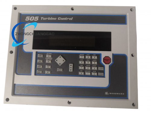
| 505E / 505D | Analog 4–20 mA (backup) |
| EASYgen-3200 | CAN bus |
| EASYgen-3500-P2 | CAN bus with redundancy |
Compatible Actuator Models (Woodward)
| Actuator Model | Type | Voltage | Force |
|---|---|---|---|
| 9907-167 | Magnetic, high-force | 24 VDC | 800 N |
| 9907-168 | Magnetic, standard-force | 12/24 VDC | 500 N |
| 9930-823 | Magnetic, high-force | 24 VDC | 1000 N |
| 9907-046 | Magnetic, low-force | 24 VDC | 200 N |
| 9907-771 | Electronic, 4–20 mA input | 24 VDC | 600 N |
| 9907-773 | Electronic, 0–10 VDC input | 24 VDC | 600 N |
| 9907-836 | Electronic, CAN bus input | 24 VDC | 800 N |
Model Series Cross-Reference
| Model | Key Difference from 5501-376 |
|---|---|
| 5501-371 | Basic position control, no CAN bus, 4 discrete I/O |
| 5501-373 | CAN bus + analog, no ESD input, 6 discrete I/O |
| 5501-376 | Full-featured: CAN bus, analog, ESD, 8 discrete I/O, IP65, 14-bit resolution |
| 5501-379 | Extended temperature range (-55°C to +105°C), military-grade |
| 5501-476 | Hazardous area rated (ATEX Zone 2, IECEx) |
Certifications and Compliance
- CE Marking — Conforms to EU Machinery Directive 2006/42/EC
- UL Listed — File E147353 (North America)
- CSA Certified — File LR78161 (Canada)
- DNV GL Type Approval — For marine installations
- Lloyd’s Register — Approved for marine generator sets
- ABS (American Bureau of Shipping) — Approved for marine use
- ATEX — Standard 5501-376 is NOT rated for hazardous areas; use 5501-476 for ATEX Zone 2
- IEC 61508 — SIL 2 capable (when used with SIL-rated engine controller)
- IEC 61000-6-2 — EMC emission and immunity for industrial environments
- IEC 60068-2-6 — Vibration resistance
- IEC 60529 — IP65 ingress protection
Part Number Breakdown
| Segment | Meaning |
|---|---|
| 5501 | Product family — Digital Actuator Controller |
| 3 | Feature set — Full function with CAN bus, ESD, 8 discrete I/O |
| 76 | Configuration code — Global standard, 24 VDC, IP65, Deutsch DT06 connector, 14-bit resolution |
Installation Requirements
- Mount on 35 mm DIN rail (EN 60715) or directly on the fuel actuator using the supplied stainless steel bracket
- Maintain minimum 50 mm clearance on all sides for ventilation and heat dissipation
- Route CAN bus cable away from high-current power cables (minimum 200 mm separation)
- Use shielded twisted-pair cable for CAN bus (120 Ω characteristic impedance, 24 AWG minimum)
- Use shielded cable for analog signals (4–20 mA or 0–10 VDC)
- Ground the controller chassis to the engine block ground point using minimum 6 AWG copper wire (green/yellow)
- Supply voltage must be 24 VDC regulated with less than 5% ripple
- Torque all terminal connections to 1.5 Nm (13.3 in-lbs)
- Verify actuator air gap is within 0.3 mm to 1.5 mm (0.012″ to 0.060″) before startup
- Install 120 Ω termination resistors at both ends of the CAN bus
- Ensure the Deutsch DT06-6S connector is fully seated and locked before energizing
Usage Precautions
- Do not exceed the maximum supply voltage of 32 VDC — permanent damage to internal components will occur
- Do not reverse the polarity of the power supply — internal 5 A fast-blow fuse will open
- Do not operate the unit in environments exceeding +85°C ambient temperature
- Do not expose the PCB to chemical solvents — silicone conformal coating will degrade
- Perform a no-load position calibration after initial installation and after any actuator replacement
- Perform a functional test of all protection relays every 6 months
- Do not modify the firmware using unauthorized tools — this voids the warranty immediately
- The unit contains no user-serviceable components — contact Woodward for all repairs
- Replace the FKM (Viton) O-rings if the IP65 seal is compromised or damaged
- Verify CAN bus termination resistors (120 Ω) are installed at both ends of the bus at all times
- Do not connect or disconnect the Deutsch DT06 connector while the unit is powered
- Store the unit in a dry environment with relative humidity below 85%
Warranty
- Standard Warranty: 24 months from date of shipment
- Extended Warranty: Available up to 60 months (Woodward Protect program)
- Warranty Exclusions: Damage caused by reverse polarity, overvoltage, physical impact, unauthorized firmware modification, or operation outside specified environmental limits
Document Reference Numbers
| Document | Number |
|---|---|
| Installation Manual | 5501-IM-001 |
| Operator’s Manual | 5501-OM-001 |
| Configuration Guide | 5501-CG-001 |
| Wiring Diagram | 5501-WD-001 |
| CAN Bus Communication Guide | 5501-CB-001 |
| Diagnostic Procedures | 5501-DP-001 |
| Firmware Update Guide | 5501-FU-001 |
| Actuator Compatibility Chart | 5501-AC-001 |
Reviews
There are no reviews yet.