Description
Technical Specifications
Functional Features
- Dual independent speed control channels (CH1 and CH2) — supports primary/backup governor configuration or twin-engine parallel operation
- Dual LVDT/RVDT position feedback inputs — accepts valve position feedback from electro-hydraulic or electronic fuel actuators for closed-loop position control
- Digital PID speed regulation with adaptive auto-tuning — automatically optimizes P, I, D gains based on engine response characteristics
- Programmable droop speed control — adjustable from 0% to 10% droop in 0.1% increments for load sharing applications
- Load sharing via CAN bus (J1939) or Modbus TCP/EtherNet/IP — up to 16 governors can be networked for precise parallel load distribution
- Built-in engine protection — overspeed trip, underspeed trip, crank failure detection, low oil pressure shutdown, high coolant temperature shutdown, overcrank protection
- Fuel cut-off relay — dedicated relay for fuel solenoid de-energization on trip condition
- Slow-down / fast-up ramp generators — programmable acceleration and deceleration rates for smooth engine start and shutdown
- Idle speed control — programmable idle speed setpoint for standby generator applications with automatic transition to rated speed on load acceptance
- Event logging — onboard non-volatile memory stores up to 1,000 time-stamped events including trips, alarms, and setpoint changes
- Self-diagnostics — continuous monitoring of speed input signal quality, LVDT feedback signal quality, actuator current, relay status, and internal CPU health
- 8 programmable Form C relay outputs — configurable for alarm, shutdown, status indication, or custom interlock functions
- Analog output — 2 configurable 4-20 mA outputs for speed, valve position, load, or engine parameter transmission to DCS/SCADA
- Web-based configuration — full parameter programming via Woodward GMT (Governor Management Tool) software over Ethernet or USB
- Redundant configuration support — dual power input terminals and dual speed input terminals for SIL 3 / redundant applications
- Built-in LVDT excitation — provides AC excitation for LVDT sensors, eliminates external LVDT power supply
- J1939 CAN bus communication — native support for engine communication with modern electronic engine controls (EEC)
- Modbus and EtherNet/IP dual protocol — integrates with any DCS, PLC, or SCADA platform
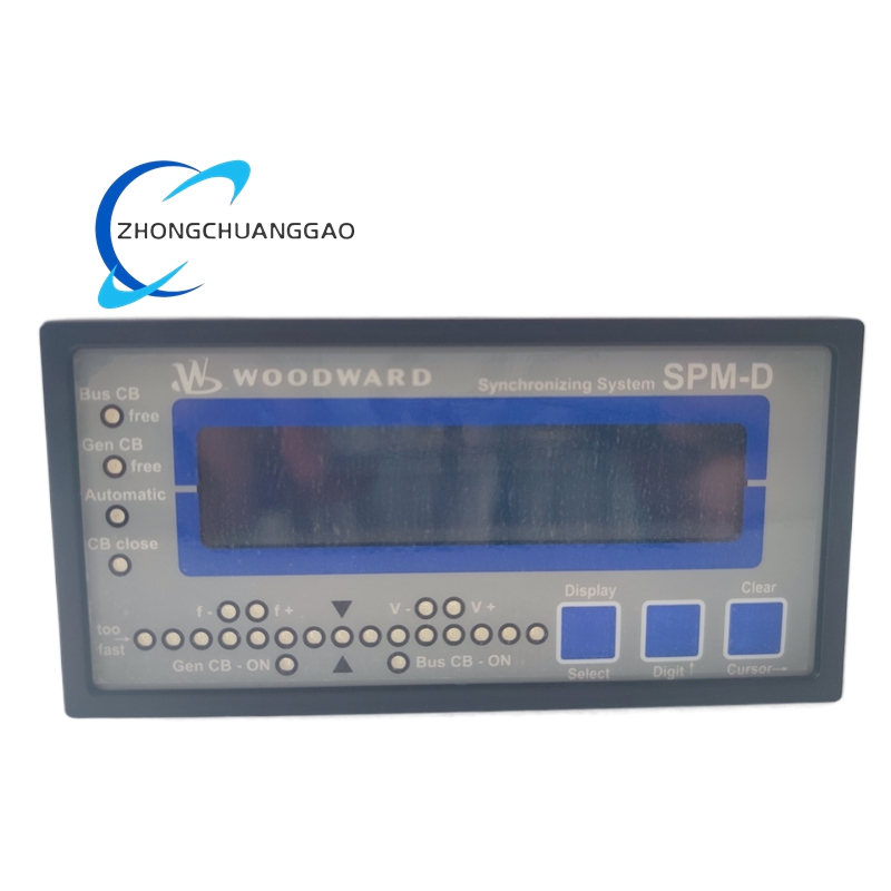
- Front-accessible LED indicators — status LEDs for power, run, alarm, trip, speed channel 1, speed channel 2, and communication activity
Performance Parameters
Material Composition
Structural Features
- Compact DIN-rail mountable enclosure — fits standard 35mm top-hat rail or panel-mount with rear bracket
- Modular I/O architecture — removable terminal blocks for speed input, LVDT input, actuator output, power, relay output, and communication
- Front-accessible LED indicators — 8 status LEDs for power, run, alarm, trip, speed CH1, speed CH2, LVDT CH1, LVDT CH2, and communication activity
- Sealed front panel — IP54 protection rating (dust and splash resistant)
- Rear cable entry — 6 cable glands (2× PG11 for speed input, 2× PG16 for LVDT input, 2× PG11 for power/comm) with knockouts
- Vibration-damped mounting — internal rubber grommets isolate PCB from enclosure vibration
- EMC shielding — full metal enclosure with grounded shielding gasket between front and rear sections
- Service access — hinged front bezel allows terminal access without full panel removal
- Heat dissipation — internal heatsink fins on power module, natural convection cooling (no fan required)
- Redundant configuration support — dual power input terminals and dual speed input terminals for SIL 3 applications
- USB configuration port — front-panel USB Type-B port for direct connection to PC for GMT software programming
- Ethernet port — rear-panel RJ-45 connector for Modbus TCP and EtherNet/IP communication
- RS-485 port — rear-panel DB-9 connector for Modbus RTU communication
- CAN bus port — rear-panel DB-9 connector for J1939 CAN bus communication
- Test button — front-panel push button for trip relay verification test
- LVDT input terminals — dedicated LVDT/RVDT input terminals with automatic excitation selection (2.5 kHz or 10 kHz)
- Actuator output terminals — heavy-gauge terminals rated for 10A continuous to actuator torque motor
- Fuse protection — internal 2A fast-blow fuse per actuator channel for overcurrent protection
Working Principle
The Woodward 8440-1713D operates as a digital closed-loop speed and position controller with integrated engine protection. The microprocessor continuously samples two independent speed signals from magnetic pickups or proximity probes mounted on the engine flywheel or camshaft via the internal 16-bit analog-to-digital converters (ADCs). Each speed channel is independently scaled from raw signal to engineering units (RPM) using programmable calibration constants. The unit applies a digital PID control algorithm with adaptive auto-tuning to calculate the required actuator position. Simultaneously, the unit receives valve position feedback from two independent LVDT or RVDT sensors mounted on the fuel actuator or gas valve actuator. The LVDT signal is conditioned by the internal signal conditioning circuit, which provides automatic AC excitation at 2.5 kHz or 10 kHz and converts the AC position signal to a DC voltage proportional to valve stroke. The microprocessor compares the commanded valve position (derived from the speed PID output) against the actual valve position feedback and calculates the position error. The onboard position PID controller processes this error and generates a corrective current output sent to the actuator driver stage (±50 mA analog or PWM). The actuator driver controls the electro-hydraulic servo valve or electronic fuel actuator, which positions the engine fuel rack or gas valve to maintain the desired speed. The unit also monitors speed input signal quality for open circuit, short circuit, and out-of-range faults, monitors LVDT signal quality for wire break and signal loss, and monitors relay status for fault detection. If an overspeed, underspeed, crank failure, or other protection condition is detected, the dedicated trip relay de-energizes within 50 ms, sending a trip signal to the engine fuel solenoid and shutting down the engine. All events, alarms, and trip conditions are time-stamped and stored in non-volatile flash memory and transmitted via Modbus RTU/TCP, EtherNet/IP, or CAN bus (J1939) to the plant DCS, SCADA, or engine monitoring system. When networked with other 8440 governors via CAN bus or Modbus TCP, the unit performs load sharing by exchanging speed and load data with peer governors, adjusting its droop setpoint to achieve equal load distribution.
Advantages and Highlights
- Dual speed and dual LVDT channels — provides redundancy and cross-checking for critical engine speed and valve position control
- Digital PID with adaptive auto-tuning — eliminates manual PID tuning, automatically optimizes control parameters for each engine
- Drop-in replacement for Woodward 505E/505F/9907 — same footprint, same I/O wiring, same connector pinout, zero redesign required
- Built-in LVDT excitation — no external LVDT power supply required, auto-detects LVDT type and excitation frequency
- J1939 CAN bus native support — direct communication with modern electronic engine controls without protocol conversion
- SIL 2 certified (SIL 3 with redundancy) — meets functional safety requirements for engine overspeed protection per IEC 61508
- 8 programmable relays — versatile interface for engine protection, alarm, status, and custom interlock functions
- Non-volatile event memory — retains 1,000 events through power loss, supports post-trip analysis
- Web-based configuration (GMT software) — full parameter programming via standard Ethernet USB or Ethernet, no proprietary hardware tools required
- Wide temperature range — operates from -20°C to +70°C, suitable for outdoor and harsh industrial environments
- Low power consumption — < 8 Watts, compatible with 24 VDC uninterruptible power supplies (UPS)
- Modbus RTU/TCP, EtherNet/IP, and CAN bus triple protocol — integrates with any DCS, PLC, SCADA, or engine monitoring platform
- Front-panel relay test button — allows periodic trip relay verification without system shutdown
- Idle speed control with auto-transition — programmable idle-to-rated speed transition for standby generator applications
- Crank failure detection — built-in engine crank monitoring with configurable timeout, prevents false starts
- Slow-down / fast-up ramp control — programmable ramp rates protect engine from thermal shock during start and stop
Applicable Industries
Model Series Comparison (Woodward 8440 Family)
Installation Requirements
- Mounting Location: Install in a clean, dry, vibration-controlled environment within 0°C to +50°C ambient temperature
- Mounting Orientation: Vertical or horizontal DIN-rail mount; maintain minimum 2 inches (50 mm) clearance above and below unit for airflow
- Vibration Isolation: Use rubber vibration isolators if mounting surface vibration exceeds 2g RMS
- Power Wiring: Use shielded twisted-pair cable, 18 AWG minimum, for 24 VDC power input; connect positive and negative to designated terminals
- Speed Input Wiring: Use shielded twisted-pair cable, 22 AWG minimum, from magnetic pickup or proximity probe to governor input; maintain minimum 6 inches (150 mm) separation from power cables
- LVDT Input Wiring: Use shielded twisted-pair cable, 22 AWG minimum, from LVDT/RVDT to governor input; do not exceed 100 feet (30 m) without signal boosting
- Actuator Output Wiring: Use shielded cable, 18 AWG minimum, from governor actuator output to servo actuator torque motor; do not exceed 50 feet (15 m) without signal boosting
- Grounding: Connect chassis ground to plant equipment ground bus using green/yellow wire, minimum 14 AWG
- Cable Gland Torque: Tighten cable glands to 15 to 20 in-lbs (1.7 to 2.3 Nm) per manufacturer specification
- Communication Wiring (Modbus RTU): Use shielded twisted-pair, 22 AWG to 24 AWG, maximum 4,000 feet (1,200 m) at 9600 baud; for EtherNet/IP, use Cat5e or Cat6 shielded Ethernet cable, maximum 100 meters (328 feet) per segment
- Communication Wiring (CAN Bus): Use shielded twisted-pair, 22 AWG, maximum 40 meters (131 feet) at 500 kbps; terminate bus with 120 Ohm resistor at each end
- Redundant Power: For SIL 2/SIL 3 applications, connect dual 24 VDC power supplies to redundant power terminals
- Trip Relay Wiring: Use 14 AWG minimum wire for trip relay contacts; wire to engine fuel solenoid per OEM specifications
- LVDT Wiring: Use shielded twisted-pair cable, 22 AWG minimum; do not mix LVDT wires with power cables in the same conduit
- Environmental Sealing: Install IP66-rated cable glands if unit is exposed to moisture or dust
- Clearance: Maintain minimum 6 inches (150 mm) clearance from high-voltage cables (> 600 VAC)
- Actuator Compatibility: Verify actuator model is Woodward 9907, 9903, or equivalent EH servo actuator before connecting actuator output
- LVDT Compatibility: Verify LVDT type is ±5 VAC or ±10 VAC, 50 Hz to 10 kHz; do not connect 0-10 VDC LVDTs without signal converter
- Speed Probe Compatibility: Verify speed probe type is magnetic pickup (passive, 30 mV minimum) or proximity probe (active, 8 Vpp minimum)
Usage Precautions and Notes
- Never apply power to the governor without all I/O connections properly terminated — open speed inputs cause false overspeed readings and unstable control
- Verify speed probe polarity before energizing — incorrect polarity causes erratic speed display and unstable control
- Do not exceed ±50 mA on actuator output channels — overcurrent damages the output driver stage and actuator torque motor
- Do not exceed 15 VAC on LVDT input channels — overvoltage damages the LVDT signal conditioning circuit
- Replace the 24 VDC power supply filter capacitor every 5 years — electrolytic capacitors degrade over time and cause power supply ripple
- Perform a full functional test including overspeed trip every 12 months per API 670 and NFPA 85 requirements
- Do not modify firmware without Woodward-authorized service personnel — unauthorized firmware changes void SIL certification
- Lock the front panel after configuration using the provided security screws to prevent unauthorized parameter changes
- Record all configuration changes in the plant maintenance log — include date, technician name, and parameter values changed
- Do not operate the governor with the front bezel removed — exposure to live terminals creates electrical hazard
- Verify communication settings (baud rate, node address, protocol, CAN bus ID) match the DCS/SCADA configuration before connecting to the network
- In the event of a speed input signal loss, the governor will trip on underspeed — this is a failsafe design, not a fault condition
- Do not use the governor for safety-instrumented functions without SIL certification verification — confirm SIL rating matches the application safety integrity level
- Battery backup for 24 VDC power is mandatory for SIL 2/SIL 3 installations — power loss must not cause uncontrolled engine shutdown
- Store spare units in a climate-controlled environment, 10°C to 35°C, with desiccant packs — moisture ingress damages PCB conformal coating
- Calibrate LVDT sensors annually — LVDT drift causes position control inaccuracy over time
- Calibrate speed probes annually — probe gap and signal amplitude affect speed measurement accuracy
- All installation and commissioning must be performed by a certified Woodward service technician or authorized third-party integrator per Woodward installation manual WM-0015
- When using the 8440-1713D with a J1939 CAN bus engine, verify the CAN bus ID and baud rate match the engine EEC configuration — mismatch causes governor fault
- Do not connect the 8440-1713D analog output to a DCS input with a different signal range — 4-20 mA to 4-20 mA only; do not connect to 0-10 VDC inputs without a signal converter
- The 8440-1713D provides LVDT excitation; do not apply external LVDT power to the same sensor — dual power sources damage the LVDT
- Servo output cables must be routed separately from control signal cables — electromagnetic interference from servo cables corrupts LVDT feedback signals
- Verify actuator torque motor resistance matches the 8440-1713D output rating — connecting an actuator with resistance outside the specified range causes overheating or insufficient drive current
- Do not bypass the internal fuse on any actuator channel — the fuse protects the output driver stage from catastrophic failure
- For marine installations, verify ABS/DNV/Lloyd’s/BV type approval matches the installation class — use only approved configuration files
- For hazardous area installations, verify ATEX Zone 2 certification matches the area classification — use only approved wiring methods and enclosures
- Perform a crank failure detection test during commissioning — simulate crank loss and verify trip occurs within the configured timeout
- Verify all relay outputs are wired to the correct engine protection circuits — incorrect wiring causes failure to shut down on trip condition
- All torque wrenching and bolting operations on mounting hardware must follow ASME PCC-1 — use calibrated tools and correct torque values
Reviews
There are no reviews yet.