Description
Technical Specifications
Functional Features
- Dual independent speed control channels (CH1 and CH2) — supports dual-turbine or primary/backup governor configurations
- Digital PID speed regulation — provides precise speed control with programmable proportional, integral, and derivative gains
- Load sharing capability — up to 4 governors can be networked for parallel load sharing via EtherNet/IP or Modbus
- Built-in speed ramp generator — programmable acceleration and deceleration rates for smooth startup and shutdown
- Overspeed protection — configurable overspeed trip with independent hardware trip output
- Underspeed protection — configurable underspeed trip with independent hardware trip output
- LVDT/RVDT feedback input — accepts valve position feedback for closed-loop position control
- Remote setpoint adjustment — speed setpoint adjustable via analog input (4-20 mA or 0-10 VDC) or digital communication
- Event logging — onboard non-volatile memory stores up to 500 time-stamped events
- Self-diagnostics — continuous monitoring of speed input signal quality, actuator current, and internal CPU health
- Trip relays — 2 independent Form C trip relays (overspeed, underspeed) with configurable de-energize-to-trip or energize-to-trip logic
- Auxiliary relay outputs — 4 programmable Form C auxiliary relays for status indication, alarm, or interlock functions
- Analog output — 1 configurable 4-20 mA output for speed, valve position, or load indication
- Web-based configuration — full parameter programming via Woodward GMT (Governor Management Tool) software over Ethernet
Performance Parameters
Material Composition
Structural Features
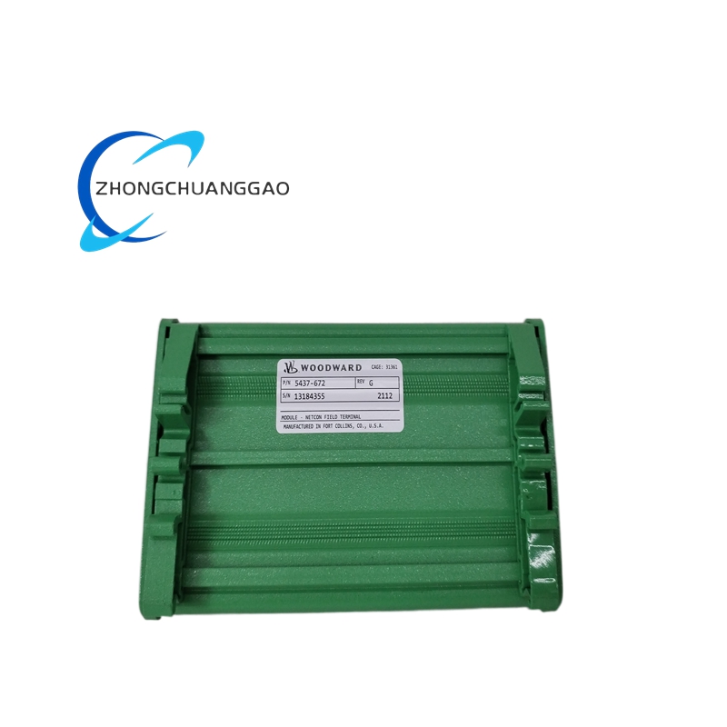
- Compact DIN-rail mountable enclosure — fits standard 35mm top-hat rail or panel-mount with rear bracket
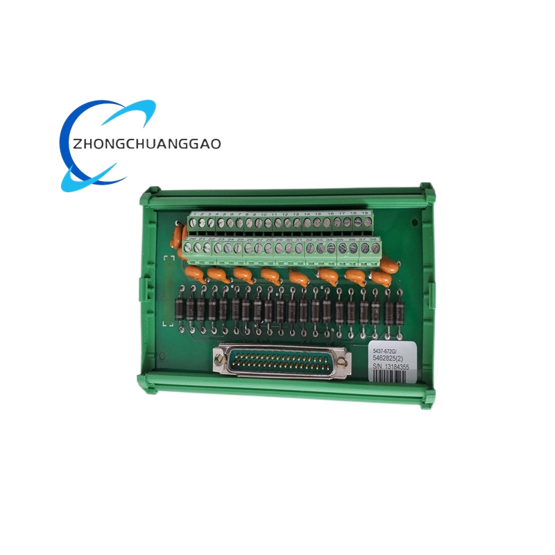
- Modular I/O architecture — removable terminal blocks for speed input, actuator output, power, and communication
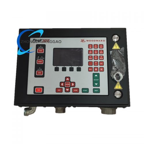
- Front-accessible LED indicators — status LEDs for power, run, alarm, trip, and communication activity
- Sealed front panel — IP54 protection rating (dust and splash resistant)
- Rear cable entry — 4 cable glands (2× PG11 for I/O, 2× PG16 for power/comm) with knockouts
- Vibration-damped mounting — internal rubber grommets isolate PCB from enclosure vibration
- EMC shielding — full metal enclosure with grounded shielding gasket between front and rear sections
- Service access — hinged front bezel allows terminal access without full panel removal
- Heat dissipation — internal heatsink fins on power module, natural convection cooling (no fan required)
- Redundant configuration support — dual power input terminals for redundant 24 VDC supplies
Working Principle
The Woodward 5437-672 operates as a digital closed-loop speed controller. The microprocessor continuously samples speed feedback signals from magnetic pickups or proximity probes mounted on the turbine shaft. The raw signal is converted to a digital frequency count and compared against the programmed speed setpoint. The internal PID controller calculates the error (difference between setpoint and actual speed) and generates a corrective output signal. This output is sent to the dual servo-valve driver channels as a ±50 mA current signal. The servo valves modulate hydraulic oil pressure to the electro-hydraulic actuator, which positions the turbine fuel or steam control valve. The system continuously adjusts valve position to maintain the desired speed. Simultaneously, the governor monitors LVDT/RVDT valve position feedback for closed-loop position control. Overspeed and underspeed protection circuits operate independently of the main PID loop, providing hardware-level trip functionality that de-energizes the turbine trip solenoid if speed exceeds or falls below preset limits. All events, alarms, and trip conditions are time-stamped and stored in non-volatile flash memory and transmitted via Modbus or EtherNet/IP to the plant DCS or SCADA system.
Advantages and Highlights
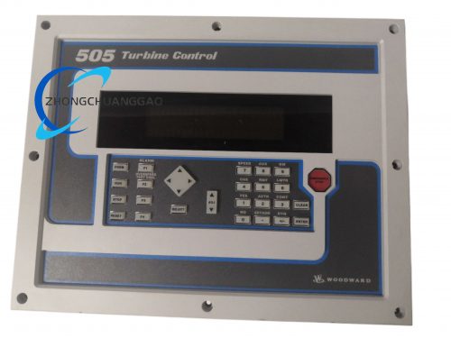
- Drop-in replacement for Woodward 505/505E — same footprint, same I/O wiring, same connector pinout, zero redesign required
- Dual independent control channels — enables primary/backup governor or twin-turbine configurations from a single unit
- Digital PID control — eliminates mechanical drift, provides repeatable and tunable speed regulation
- Load sharing via EtherNet/IP — up to 4 governors networked for precise parallel load distribution without droop compensation hardware
- SIL 2 certified (SIL 3 with redundancy) — meets functional safety requirements for turbine protection per IEC 61508
- Built-in overspeed and underspeed hardware trips — independent of software, failsafe operation
- Non-volatile event memory — retains 500 events through power loss, supports post-trip analysis
- Web-based configuration (GMT software) — full programming via standard Ethernet, no proprietary hardware tools required
- Wide temperature range — operates from -20°C to +70°C, suitable for outdoor and harsh industrial environments
- Low power consumption — < 8 Watts, compatible with 24 VDC uninterruptible power supplies (UPS)
- Modbus and EtherNet/IP dual protocol — integrates with any DCS, PLC, or SCADA platform
- No moving parts in control loop — zero mechanical wear, maintenance-free speed sensing
Applicable Industries
Model Series Comparison (Woodward 5400 / 5437 Family)
Installation Requirements
- Mounting Location: Install in a clean, dry, vibration-controlled environment within 0°C to +50°C ambient temperature
- Mounting Orientation: Vertical or horizontal DIN-rail mount; maintain minimum 2 inches (50 mm) clearance above and below unit for airflow
- Vibration Isolation: Use rubber vibration isolators if mounting surface vibration exceeds 2g RMS
- Power Wiring: Use shielded twisted-pair cable, 18 AWG minimum, for 24 VDC power input; connect positive and negative to designated terminals
- Speed Input Wiring: Use shielded twisted-pair cable, 22 AWG minimum, from magnetic pickup to governor input; maintain minimum 6 inches (150 mm) separation from power cables
- Actuator Output Wiring: Use shielded cable, 18 AWG minimum, from governor servo output to actuator solenoid; do not exceed 50 feet (15 m) without signal boosting
- Grounding: Connect chassis ground to plant equipment ground bus using green/yellow wire, minimum 14 AWG
- Cable Gland Torque: Tighten cable glands to 15 to 20 in-lbs (1.7 to 2.3 Nm) per manufacturer specification
- Communication Wiring: For Modbus RTU, use shielded twisted-pair, 22 AWG to 24 AWG, maximum 4,000 feet (1,200 m) at 9600 baud; for EtherNet/IP, use Cat5e or Cat6 shielded Ethernet cable, maximum 100 meters (328 feet) per segment
- Redundant Power: For SIL 2/SIL 3 applications, connect dual 24 VDC power supplies to redundant power terminals
- Trip Relay Wiring: Use 14 AWG minimum wire for trip relay contacts; wire to turbine trip solenoid per OEM specifications
- Environmental Sealing: Install IP66-rated cable glands if unit is exposed to moisture or dust
- Clearance: Maintain minimum 6 inches (150 mm) clearance from high-voltage cables (> 600 VAC)
Usage Precautions and Notes
- Never apply power to the governor without all I/O connections properly terminated — open speed inputs cause false overspeed readings
- Verify speed pickup polarity before energizing — incorrect polarity causes erratic speed display and unstable control
- Do not exceed ±50 mA on servo output channels — overcurrent damages the output driver stage
- Replace the 24 VDC power supply filter capacitor every 5 years — electrolytic capacitors degrade over time and cause power supply ripple
- Perform a full functional test including overspeed trip every 12 months per API 670 and NFPA 85 requirements
- Do not modify firmware without Woodward-authorized service personnel — unauthorized firmware changes void SIL certification
- Lock the front panel after configuration using the provided security screws to prevent unauthorized parameter changes
- Record all configuration changes in the plant maintenance log — include date, technician name, and parameter values changed
- Do not operate the governor with the front bezel removed — exposure to live terminals creates electrical hazard
- Verify communication settings (baud rate, node address, protocol) match the DCS/SCADA configuration before connecting to the network
- In the event of a speed input signal loss, the governor will trip on underspeed — this is a failsafe design, not a fault condition
- Do not use the governor for safety-instrumented functions without SIL certification verification — confirm SIL rating matches the application safety integrity level
- Battery backup for 24 VDC power is mandatory for SIL 2/SIL 3 installations — power loss must not cause uncontrolled turbine shutdown
- Store spare units in a climate-controlled environment, 10°C to 35°C, with desiccant packs — moisture ingress damages PCB conformal coating
- All installation and commissioning must be performed by a certified Woodward service technician or authorized third-party integrator per Woodward installation manual WM-0015
Reviews
There are no reviews yet.