Product Short Description
Product Category: Digital Electro-Pneumatic Positioner / Actuator Controller
Control Type: Proportional closed-loop position control
Communication Protocol: HART 7 (Highway Addressable Remote Transducer) — simultaneous analog and digital communication
Feedback Type: Rotary (10–100°) or Linear (10–100 mm) depending on configuration
Control Action: Direct acting (air-to-open) or Reverse acting (air-to-close) — field selectable
Description
Input Signal: 4–20 mA DC (two-wire, loop-powered)
Output Signal: 3–15 psi (0.2–1.0 bar) pneumatic
Supply Voltage: 24 VDC nominal, operating range 18–32 VDC
Supply Air Pressure: 80 psi (5.5 bar) regulated, clean, dry, oil-free air required
Maximum Supply Pressure: 100 psi (6.9 bar) — do not exceed
Air Consumption: Less than 1.5 SCFM at full stroke
Signal Wiring: Two-wire loop, 18 AWG minimum, shielded twisted pair recommended in high-EMI environments
Accuracy: ±0.5% of full stroke
Linearity: ±0.25% of full stroke
Repeatability: ±0.1% of full stroke
Deadband: Less than 0.2% (adjustable via HART)
Response Time: Less than 0.5 seconds to 90% of final position
Zero Drift: Less than ±0.1% of span per year
Span Drift: Less than ±0.2% of span per year
Stroke Range: 10° to 100° rotary or 10 mm to 100 mm linear (configurable)
Operating Temperature Range: -40°C to +85°C (-40°F to +185°F)
Storage Temperature Range: -50°C to +90°C (-58°F to +194°F)
Ambient Humidity: 5% to 95% RH, non-condensing
Vibration Tolerance: Meets IEC 60068-2-6 (10–150 Hz, 1.5 g)
Shock Tolerance: Meets IEC 60068-2-27 (50 g, 11 ms)
Ingress Protection: IP66 / IP67 enclosure rating
Enclosure Rating: NEMA 4X compatible
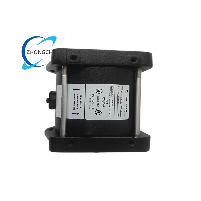
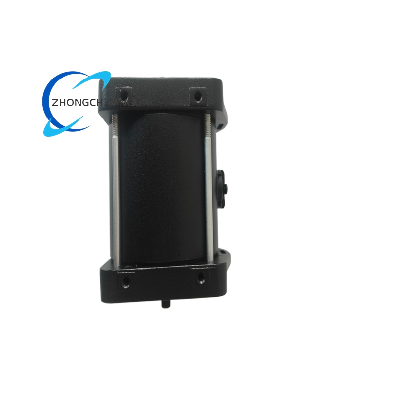
Housing Material: Cast aluminum alloy with epoxy-polyester powder coat finish (corrosion resistant)
Internal Wetted Parts: Stainless steel 316L
Diaphragm Material: Nitrile rubber (NBR) standard; Fluoroelastomer (FKM / Viton) available as option
O-Rings / Seals: FKM (Viton) or EPDM depending on temperature and media
Electrical Connectors: 1/2″ NPT conduit entries, DIN 43650 form A connector compatible
Mounting Bracket: Cast aluminum with stainless steel hardware
Feedback Linkage: Stainless steel 304 lever arm and pivot pin
Structure:
- Compact modular digital housing with integrated I/P (current-to-pneumatic) converter, pneumatic relay amplifier, digital signal processor (DSP), and mechanical feedback linkage in a single enclosure
- Mounting Options: Direct mount on actuator (top-mount or side-mount) or wall/panel mount with bracket
- Dimensions (approximate): 200 mm × 140 mm × 160 mm (L × W × H)
- Weight: Approximately 3.2 kg (7.0 lbs) without mounting bracket
- Feedback Type: Rotary or linear mechanical feedback via adjustable lever arm and cam mechanism
- Front Panel: LED status indicators (power, signal, fault, HART communication) with push-button navigation
Working Principle:
The 4–20 mA DC input current energizes an internal torque motor (flapper-nozzle assembly) controlled by a digital signal processor (DSP). The DSP compares the input signal against the actual valve position reported by the mechanical feedback linkage. Any error between the commanded position and actual position generates a correction signal that modulates the flapper-nozzle backpressure. This modulates a pneumatic relay (pilot stage), which amplifies the signal to produce a proportional 3–15 psi output pressure. This output acts on the actuator piston or diaphragm to move the valve. When the valve reaches the commanded position, the feedback signal matches the input signal, the flapper returns to null, and the output pressure stabilizes. The HART 7 protocol overlays digital data on the 4–20 mA signal, enabling remote configuration, calibration, and diagnostics.
Key Features:
- Full digital architecture with DSP-based control — superior accuracy and stability compared to analog positioners
- HART 7 protocol — remote calibration, diagnostics, and configuration via handheld communicator or DCS
- LED status indicators — power ON, signal present, fault/alarm, HART communication active
- Adjustable zero and span — field calibration via push buttons or HART communicator
- Fail-safe configurations — air-to-open (ATO) or air-to-close (ATC) with spring return, field selectable
- Intrinsically safe option available — certified for Zone 1 / Zone 2 hazardous areas (ATEX, IECEx)
- SIL 2 capable — when used with approved safety instrumented functions (IEC 61508 / IEC 61511)
- Auto-tuning — DSP automatically optimizes control parameters for the connected actuator
Advantages:
- ±0.5% accuracy — industry-leading precision for tight process control loops
- Less than 0.5 second response time — fast dynamic response for demanding applications
- HART 7 digital diagnostics — remote troubleshooting reduces downtime and eliminates site visits
- Auto-tuning DSP — eliminates manual gain adjustment; the positioner self-optimizes
- Low air consumption (under 1.5 SCFM) — reduces compressed air operating costs
- Robust IP66/IP67 NEMA 4X enclosure — suitable for outdoor, washdown, and harsh indoor environments
- Simple two-wire installation — minimizes wiring complexity and cost
- Long-term stability — digital architecture eliminates drift associated with analog potentiometers
Applicable Industries:
- Power Generation — gas turbine fuel control, steam turbine governing, boiler feedwater regulation, damper control
- Oil & Gas — refinery process control, pipeline valve regulation, LNG plant control, wellhead choke control
- Chemical / Petrochemical — flow, pressure, and temperature control valves in continuous process
- Pulp & Paper — steam and air damper actuation, white water control
- Water / Wastewater — valve position control in treatment and distribution systems
- Mining / Metals — process valve control in harsh, dusty environments
- Food & Beverage — washdown-rated positions on processing and packaging lines
Model Series:
| Model Number | Key Differentiator |
|---|---|
| 8256-016 | Standard digital positioner, 3–15 psi output, HART 7 |
| 8256-017 | Intrinsically safe, Zone 1 rated |
| 8256-018 | SIL 2 certified, safety-rated |
| 8256-019 | Double-acting actuator control |
| 8256-020 | Linear feedback, 10–100 mm stroke |
| 8256-021 | Extended temperature range, -55°C to +100°C |
Feedback Configuration:
| Feedback Type | Stroke Range | Application |
|---|---|---|
| Rotary | 10° to 100° | Butterfly valves, ball valves, dampers |
| Linear | 10 mm to 100 mm | Globe valves, sliding stem valves |
Control Action Configuration:
| Setting | Description |
|---|---|
| Direct Acting (ATO) | Increasing signal = increasing output pressure = valve opens |
| Reverse Acting (ATC) | Increasing signal = decreasing output pressure = valve closes |
Installation Requirements:
- Mount the positioner on a rigid, vibration-free surface using the provided mounting bracket
- Align the feedback linkage precisely with the valve stem travel range during commissioning
- Provide clean, dry, oil-free air supply at 80 psi (5.5 bar) with an air filter-regulator-lubricator (FRL) upstream of the positioner
- Ensure proper electrical grounding per NEC Article 500 / IEC 60079 standards
- Use shielded twisted-pair cable for signal wiring in high-EMI environments
- Verify supply voltage is within 18–32 VDC before energizing
- Set zero and span after mechanical installation is complete using push buttons or HART communicator
- Confirm fail-safe direction (ATO vs ATC) matches process safety requirements before commissioning
Usage Precautions:
- Do not exceed maximum supply pressure of 100 psi (6.9 bar) — this will damage internal diaphragm and seals
- Do not operate without an air filter — particulate contamination will destroy the flapper-nozzle assembly and relay
- Do not apply voltage exceeding 32 VDC — this will burn out the torque motor coil and DSP
- Do not expose to temperatures below -40°C or above +85°C — performance is not guaranteed outside this range
- Verify fail-safe direction (ATO vs ATC) matches process safety requirements before commissioning
- Perform zero and span calibration after installation and at scheduled intervals (typically annually)
- Replace diaphragm and seals per maintenance schedule — typically every 2–3 years in harsh service
- Do not disassemble in hazardous (classified) areas unless the unit carries the appropriate certification for that zone
- Do not exceed 100 psi (6.9 bar) washdown pressure — direct high-pressure jet can force water past the seal over time
- Verify HART communication with the DCS before relying on remote diagnostics — mismatch causes communication failure
Certifications:
- ATEX Zone 1 / Zone 2 (with intrinsically safe option, model 8256-017)
- IECEx certified
- SIL 2 capable (IEC 61508 / IEC 61511, with appropriate safety functions, model 8256-018)
- UL Listed / CSA Certified
- CE Marked (EU Machinery Directive 2006/42/EC, Low Voltage Directive 2014/35/EU, EMC Directive 2014/30/EU)
- FM Approved (for North American hazardous locations, Class I Division 2)
- RoHS Compliant (Directive 2011/65/EU)
- REACH Compliant (Regulation EC 1907/2006)
Documentation Reference:
- Woodward 8256 Series Installation & Operation Manual (Form 8256-IM-001)
- Woodward 8256 Series Technical Data Sheet (Form 8256-TDS-001)
- Woodward HART 7 Communication Protocol Guide (Form 8256-HC-001)
- Woodward Safety Manual — SIL / Functional Safety (Form 8256-SM-001)
- Woodward Positioner Selection Guide (Form 8256-SG-001)
Replacement Parts:
| Part Number | Description |
|---|---|
| 8256-DIA-001 | Diaphragm assembly, NBR |
| 8256-DIA-002 | Diaphragm assembly, FKM (Viton) |
| 8256-SEL-001 | O-ring kit, FKM |
| 8256-SEL-002 | O-ring kit, EPDM |
| 8256-FN-001 | Flapper-nozzle assembly |
| 8256-TM-001 | Torque motor coil assembly |
| 8256-RL-001 | Pneumatic relay assembly |
| 8256-FB-001 | Feedback linkage assembly, rotary |
| 8256-FB-002 | Feedback linkage assembly, linear |
| 8256-PCB-001 | Digital control PCB assembly (DSP) |
| 8256-LED-001 | LED indicator board assembly |
| 8256-CON-001 | DIN 43650 electrical connector |
| 8256-BRK-001 | Mounting bracket assembly |

Reviews
There are no reviews yet.