Product Short Description
Product Category: Snap-Action Limit Switch (Plunger Actuator)
Switch Configuration: Single-Pole Double-Throw (SPDT) — 1 NO + 1 NC contact set
Contact Rating: 15 A @ 125/250 VAC, 10 A @ 30 VDC, 10 A @ 125/250 VAC (resistive load)
Electrical Life: 100,000 operations at full rated load
Mechanical Life: 10,000,000 operations minimum
Description
Actuator Type: Short-Travel Plunger with 0.5″ (12.7 mm) Diameter Tip
Plunger Travel: 0.187″ (4.75 mm) total travel
Operating Force: 2 lbs (8.9 N) max at plunger tip
Release Force: 0.4 lbs (1.8 N) min at plunger tip
Overtravel: 0.031″ (0.8 mm) positive / 0.005″ (0.13 mm) negative
Operating Speed: 0.1 to 10 inches per second (2.5 to 254 mm/s)
Plunger Tip Material: Stainless steel 304 (standard); Delrin (acetal) available as option
Operating Temperature Range: -40°C to +85°C (-40°F to +185°F)
Storage Temperature Range: -50°C to +90°C (-58°F to +194°F)
Ambient Humidity: 5% to 95% RH, non-condensing
Vibration Tolerance: 10–500 Hz, 10 g (operating); 10–500 Hz, 20 g (survival)
Shock Tolerance: 50 g, 11 ms half-sine pulse
Ingress Protection: IP67 (body); IP66 with cover mated
Enclosure Rating: NEMA 4, 4X, 12, 13
Housing Material: Zinc die-cast alloy with epoxy-polyester powder coat finish (standard green)
Internal Contact Material: Silver alloy (AgSnO₂) for high-current switching
Terminals: Brass alloy, tin-plated
Plunger Tip: Stainless steel 304 (standard); Delrin (acetal) or Nylon 6/6 available
Seals: Silicone rubber (standard); FKM (Viton) available as option
Mounting Hardware: Stainless steel 304 screws included
Structure:
- Compact rectangular body (approximately 2.25″ × 1.75″ × 1.5″ / 57 mm × 44 mm × 38 mm)
- Top-mounted plunger actuator with sealed guide tube
- Cable entry: 1/2″ NPT conduit fittings (top and bottom)
- Prewired leads: 18 AWG, 6″ (152 mm) long, color-coded (red, black, white)
- Terminal type: Quick-connect spade terminals (0.250″ / 6.35 mm)
- Weight: Approximately 0.45 lbs (0.20 kg)
Working Principle:
The switch contains an internal snap-action mechanism with a spring-loaded over-center contact assembly. When the external plunger tip is depressed by a machine part, it pushes the internal actuator rod downward. At the switch point (actuation point), the over-center spring mechanism releases stored energy, causing the contacts to snap rapidly from one position to the other. This snap action ensures fast, clean contact transition (less than 1 ms) regardless of actuator speed within the specified range. The positive overtravel guarantees complete contact closure even if the actuating force continues after the switch point.
Key Features:
- Heavy-duty 15 A SPDT contact rating — handles high inductive and resistive loads directly
- Short-travel plunger actuator — compact footprint, ideal for tight-space installations
- IP67 / NEMA 4X sealed body — fully protected against water ingress and dust
- Adjustable switch point — internal cam position can be set to tune the actuation point
- Stainless steel plunger tip — resists corrosion, wear, and impact
- Quick-connect spade terminals — fast wiring, no tools required
- 10 million cycle mechanical life — extremely long service life in continuous duty
Advantages:
- Fast snap-action (less than 1 ms contact transition) prevents arcing, contact welding, and electrical noise
- High 15 A contact rating eliminates the need for interposing relays in most applications
- Plunger actuator provides axial force resistance — superior to lever types in high-vibration environments
- IP67 / NEMA 4X enclosure — suitable for outdoor, washdown, and food-grade environments
- Compact size fits into tight machine enclosures where lever switches cannot reach
- Long mechanical life (10M cycles) drastically reduces maintenance frequency and downtime
- Adjustable actuation point allows field tuning without replacing the switch
Applicable Industries:
- Manufacturing / Machine Tools — end-of-travel detection on presses, stamping machines, CNC equipment
- Material Handling — conveyor position sensing, hoist limit detection, crane travel stops
- Food & Beverage — washdown-rated positions on packaging, bottling, and processing lines
- Mining & Heavy Equipment — boom, bucket, and cylinder position limits on excavators and loaders
- Power Generation — valve position feedback, turbine governor limits, breaker mechanism detection
- Automotive — assembly line position sensing, robotic cell interlocks, welding fixture stops
- Oil & Gas — valve actuation feedback, pump control interlocks, pipeline pig detection
- Pulp & Paper — paper guide position sensing, roller travel limits
- Water / Wastewater — valve and gate position control in treatment and distribution systems
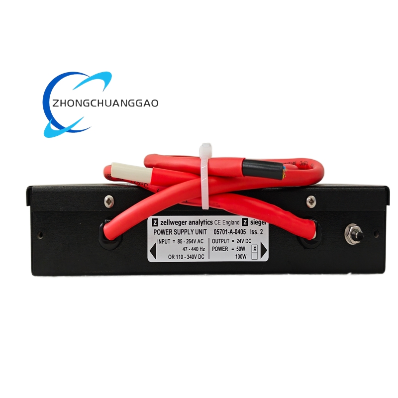
Model Series:
| Model Number | Actuator Type |
|---|---|
| 05701-A-0405 | Top plunger, 0.5″ stainless tip |
| 05701-A-0406 | Top plunger, 0.5″ Delrin tip |
| 05701-B-0405 | Side plunger, 0.5″ stainless tip |
| 05701-C-0405 | Bottom plunger, 0.5″ stainless tip |
| 05701-D-0405 | Heavy-duty plunger, 0.75″ tip |
Contact Configuration:
| Wire Color | Terminal Function |
|---|---|
| Red wire | Common (C) |
| Black wire | Normally Open (NO) |
| White wire | Normally Closed (NC) |
Installation Requirements:
- Mount the switch on a rigid, vibration-free surface using the provided 1/2″ mounting holes
- Align the plunger tip so that the actuating surface contacts the plunger perpendicular to the travel axis at the desired switch point
- Set the actuation point by adjusting the internal cam position before final tightening
- Use 1/2″ NPT conduit for cable entry; seal unused entries with the provided plugs
- Connect wires to quick-connect spade terminals; ensure connections are tight to prevent arcing
- Provide a dedicated ground connection if the switch is used in a safety-rated circuit
- Maintain a minimum 0.5″ (12.7 mm) clearance around the plunger for free movement
Usage Precautions:
- Do not exceed the rated contact current of 15 A — overloading will weld contacts and destroy the switch
- Do not operate the switch without the plunger tip in contact with the actuating surface — free plunger movement causes premature internal wear
- Do not apply side loads greater than 3 lbs (13.3 N) to the plunger tip — this will bend the guide tube
- Do not disassemble the switch in hazardous (classified) areas unless the unit carries the appropriate certification
- Verify contact configuration (NO/NC) matches the control circuit before energizing
- Perform periodic inspection of the plunger tip and seal for wear, cracks, or corrosion
- Replace the switch if the plunger tip shows flat spots, the guide tube is bent, or contacts show pitting or welding
- Do not use in temperatures below -40°C or above +85°C — seal integrity and contact performance are not guaranteed outside this range
- Do not exceed 100 psi (6.9 bar) washdown pressure — direct high-pressure jet can force water past the seal over time
Certifications:
- UL Listed (File E29549)
- CSA Certified (File LR42403)
- CE Marked (Low Voltage Directive 2014/35/EU, EMC Directive 2014/30/EU, Machinery Directive 2006/42/EC)
- RoHS Compliant (Directive 2011/65/EU)
- IP67 (IEC 60529)
- NEMA 4, 4X, 12, 13 (UL 50 / NEMA 250)
Documentation Reference:
- Honeywell Micro Switch Heavy-Duty Snap-Action Catalog (Document 5000-001)
- Honeywell 05701 Series Installation Manual (Document 50701-IM-001)
- Honeywell Limit Switch Selection Guide (Document 5000-SG-001)
- Honeywell 05701 Series Technical Data Sheet (Document 50701-TDS-001)
Replacement Parts:
| Part Number | Description |
|---|---|
| 05701-1-001 | Complete switch assembly, top plunger |
| 05701-1-003 | Plunger tip assembly, 0.5″ stainless steel |
| 05701-1-006 | Plunger tip assembly, 0.5″ Delrin |
| 05701-1-010 | Contact block, 1 NO + 1 NC, 15 A |
| 05701-1-015 | Plunger rod and guide tube assembly |
| 05701-1-020 | Internal cam and spring assembly |
| 05701-1-030 | Conduit fittings, 1/2″ NPT (set of 2) |
| 05701-1-040 | Seal kit, silicone rubber |
| 05701-1-050 | Seal kit, FKM (Viton) |
-500x500.jpg)
-500x500.jpg)
Reviews
There are no reviews yet.