Product Short Description
Product Introduction:
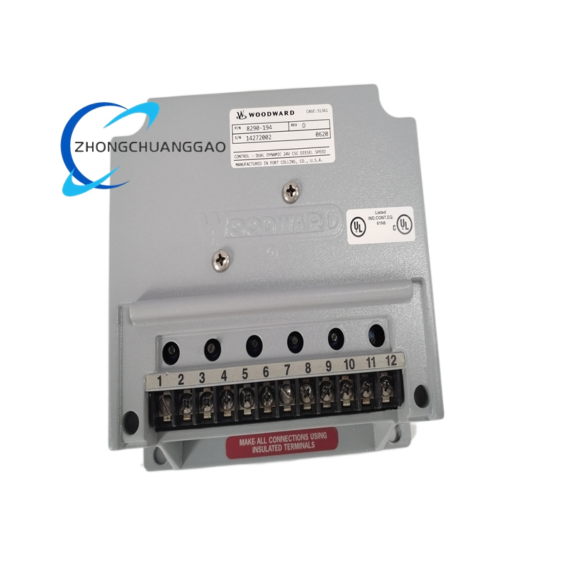
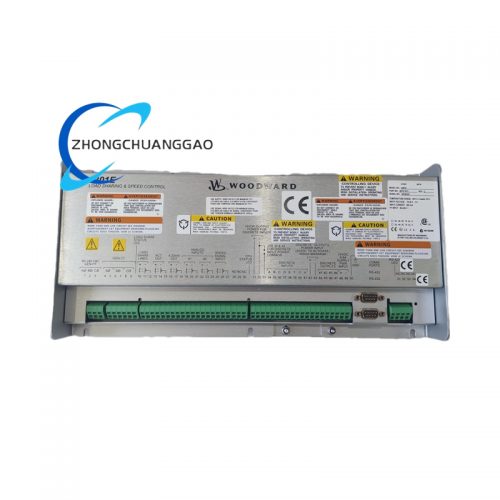
The Woodward 8290-194 is a digital electronic governor controller from the Easygen series, serving as the core speed control unit for prime movers in standby and continuous power generation systems. It replaces legacy electro-mechanical governors with a fully programmable digital platform. The 8290-194 provides speed regulation, load sharing, voltage regulation, and engine protection functions in a single compact module.
Description
Technical Specifications:
- Model Number: 8290-194
- Manufacturer: Woodward, Inc. (Honeywell)
- Series: Easygen 3000
- Controller Type: Digital Microprocessor-Based Governor
- Input Signals: Magnetic speed pickup (MPU), 4–20 mA, 0–10 VDC, frequency input (45–65 Hz)
- Output Signals: Dual proportional servo outputs (0–5 VDC or 4–20 mA), relay outputs (4× SPDT dry contacts)
- Power Supply: 24 VDC nominal (18–32 VDC range)
- Communication: RS-485 (Modbus RTU), CAN bus, Ethernet (via option card)
- Display: 128×64 pixel backlit LCD with 4 navigation buttons
- Programming: Front-panel buttons or Woodward Toolbox software via RS-485/Ethernet
- Protection Functions: Overspeed, underspeed, overfrequency, underfrequency, high coolant temp, low oil pressure, overcurrent, reverse power
- Mounting: DIN rail (EN 60715, 35 mm) or panel mount
- Operating Temperature: -20°C to +70°C (-4°F to +158°F)
- Storage Temperature: -40°C to +85°C (-40°F to +185°F)
Functional Features:
- Dual Proportional Servo Outputs: Independently controls fuel actuator and valve position with 0.1% resolution
- Isochronous and Droop Speed Control: Switchable between 0% droop (isochronous) and 4–5% droop for grid or island operation
- Load Sharing: Supports up to 16 generators in parallel via droop-based load sharing without master-slave architecture
- Voltage Regulation (AVR Interface): Provides voltage setpoint and regulation when paired with Woodward voltage regulators
- Engine Protection Suite: 8 configurable protection relays with adjustable setpoints and time delays
- Frequency Bias: Adjustable frequency bias for load-dependent speed correction in droop mode
- Ramp Rate Control: Programmable acceleration and deceleration ramp rates from 0.1 to 100% per second
- Remote Start/Stop: Digital inputs for remote start, stop, and emergency shutdown via dry contacts
- Event Logging: Stores last 100 events with timestamps for fault diagnosis
- Front-Panel Navigation: Full configuration via LCD menu and 4 push buttons; no laptop required for basic setup
- Password Protection: 3-level access control (viewer, user, engineer) prevents unauthorized changes
Performance Parameters:
| Parameter | Value |
|---|---|
| Speed Input Range | 45 Hz to 65 Hz (magnetic pickup) |
| Speed Input Sensitivity | 10 mV to 100 VAC (adjustable) |
| Speed Regulation Accuracy | ±0.1% of setpoint (isochronous) |
| Droop Accuracy | ±0.1% of rated droop |
| Servo Output Resolution | 12-bit (0.1% of full scale) |
| Servo Output Update Rate | 10 ms (100 Hz) |
| Relay Output Rating | 5 A @ 30 VDC / 250 VAC (SPDT, Form C) |
| Digital Inputs | 8× dry contact inputs (sink/source selectable) |
| Digital Outputs | 4× transistor outputs (NPN, 50 mA max) |
| Analog Inputs | 2× (4–20 mA or 0–10 VDC, 16-bit resolution) |
| Analog Outputs | 2× (0–5 VDC or 4–20 mA, 12-bit resolution) |
| Communication Baud Rate | 9600 to 115200 bps (RS-485) |
| Protocol | Modbus RTU (master/slave), CAN 2.0B |
| Power Consumption | <5 W at 24 VDC |
| Dimensions (W×H×D) | Approximately 144 × 127 × 90 mm (5.67 × 5.00 × 3.54 in) |
| Weight | Approximately 0.65 kg (1.43 lbs) |
| Enclosure Rating | IP20 (indoor use only) |
Material Composition:
- Housing: UL 94V-0 flame-retardant polycarbonate/ABS blend (dark gray)
- Front Panel: Polycarbonate overlay with membrane keypad and LCD window
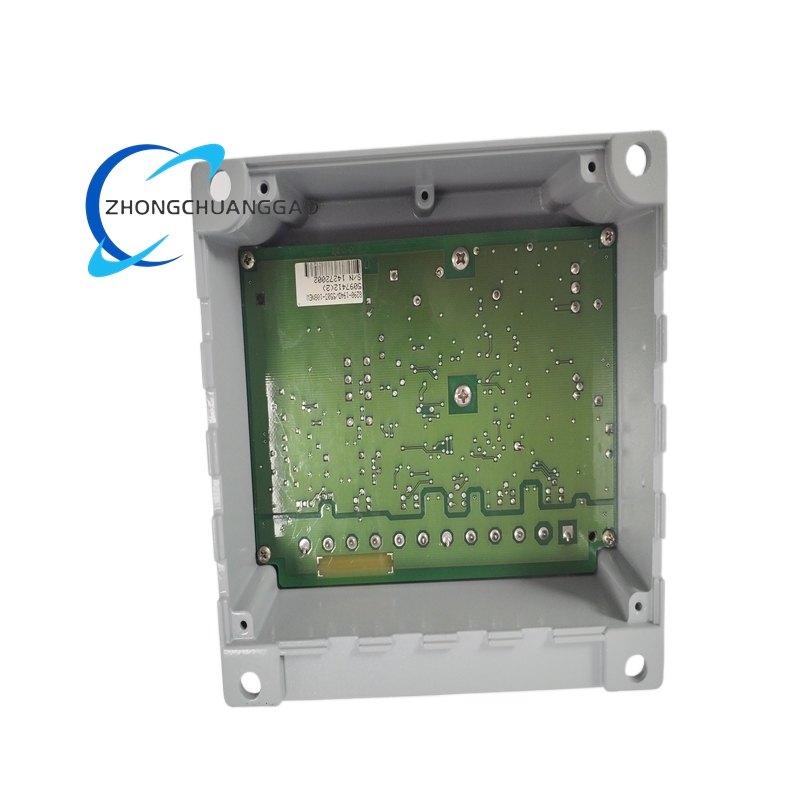
- PCB: FR-4 fiberglass epoxy laminate, conformal coated (ISO 16750 compliant)
- Terminal Blocks: Tin-plated phosphor bronze with screw-clamp connections
- Connectors: Molex Micro-Fit 3.0 series for internal wiring; Phoenix Contact for external I/O
- LCD Module: FSTN transflective LCD with LED backlight (white/amber)
- Internal Wiring: 22–26 AWG stranded tinned copper with PVC insulation
- DIN Rail Clip: Zinc-plated spring steel with locking tab
- Gaskets: Silicone rubber seal around front panel for dust protection
Structural Features:
- Compact DIN Rail Module: Single-width design fits on standard 35 mm top-hat rail
- Front Panel Layout: 128×64 LCD on left; 4 membrane navigation buttons (Up, Down, Enter, Esc) on right; LED status indicators (Power, Run, Fault, Alarm) along bottom edge
- Rear Panel: DIN rail clip, 2× analog input terminals, 2× analog output terminals, 8× digital input terminals, 4× relay output terminals, 4× digital output terminals, RS-485 terminal block, 24 VDC power terminal block, CAN bus connector
- Terminal Blocks: Screw-type terminals rated for 14–22 AWG wire; color-coded per function
- Side Vents: Small ventilation slots on both sides for passive cooling
- Bottom Cover: Removable bottom cover for terminal wiring access
- Top Cover: Fixed top cover with DIN rail mounting flange
Working Principle:
The Woodward 8290-194 receives a speed signal from a magnetic pickup (MPU) mounted on the engine flywheel or gear. The MPU generates an AC voltage proportional to engine speed (frequency). The controller’s internal frequency-to-digital converter measures the input frequency with ±0.01 Hz resolution. The measured speed is compared to the user-programmed speed setpoint in the internal PID control loop. The PID controller calculates the error (setpoint minus actual speed) and generates a correction signal sent to the dual proportional servo outputs. Output 1 drives the fuel actuator (increasing or decreasing fuel flow); Output 2 drives the auxiliary valve (for starting, shutdown, or load limiting). In isochronous mode (0% droop), the controller maintains exact setpoint speed regardless of load changes. In droop mode (4–5%), speed decreases proportionally with load increase, enabling parallel load sharing among multiple generators without a master controller. The 8 protection relays continuously monitor engine parameters; if any parameter exceeds its setpoint for longer than its time delay, the corresponding relay activates, sending a shutdown signal to the fuel actuator and triggering the emergency stop output. The RS-485 interface allows remote monitoring and configuration via Woodward Toolbox software or a SCADA system using Modbus RTU protocol.
Advantages and Highlights:
- Full Digital Replacement: Eliminates all electro-mechanical components; zero drift over time
- Front-Panel Programming: Complete setup via LCD and buttons; no laptop required for commissioning
- Dual Servo Outputs: Independent control of fuel and auxiliary valve with 12-bit resolution
- Isochronous + Droop: Single unit supports both grid-tied (droop) and standalone (isochronous) operation
- 16-Generator Load Sharing: True droop-based parallel operation without master-slave dependency
- 8 Protection Functions: Comprehensive engine protection with adjustable setpoints and time delays
- Event Logging: 100-event buffer with timestamps enables rapid fault diagnosis
- 3-Level Security: Viewer, User, and Engineer access levels prevent unauthorized configuration changes
- Modbus + CAN: Dual communication protocols for SCADA integration and remote monitoring
- Wide Temperature Range: Operates from -20°C to +70°C; suitable for outdoor enclosure installations
- Woodward Ecosystem: Fully compatible with Easygen 3000 alternator controllers, UGT15/UGT25 actuators, and WGCP panels
- 10-Year Design Life: Components rated for 10+ years continuous operation in industrial environments
Applicable Industries:
- Power Generation: Diesel generator sets (50 kW to 10 MW), gas turbine generators, steam turbine governors
- Oil and Gas: Pipeline compressor drives, wellhead power units, flare gas recovery turbines
- Marine: Ship propulsion diesel engines, auxiliary generators, bow thrusters
- Mining: Diesel-electric locomotive drives, haul truck power systems, underground ventilation fans
- Data Centers: Backup diesel generators (N+1 redundancy configurations)
- Hospitals: Emergency standby generators with automatic transfer switches
- Telecommunications: Cell tower backup power, central office generators
- Manufacturing: Combined heat and power (CHP) plants, cogeneration systems
- Military and Defense: Tactical generator sets, naval vessel power systems
- Renewable Energy: Biogas engine governors, waste-to-energy plant controllers
Model Series:
| Model Number | Description |
|---|---|
| 8290-101 | Single-speed input, single servo output, basic protection |
| 8290-102 | Single-speed input, dual servo output, basic protection |
| 8290-103 | Dual-speed input, dual servo output, full protection |
| 8290-192 | Dual-speed input, dual servo output, CAN bus, full protection |
| 8290-193 | Dual-speed input, dual servo output, Ethernet, full protection |
| 8290-194 | Dual-speed input, dual servo output, RS-485 + CAN, full protection (current model) |
| 8290-195 | Dual-speed input, dual servo output, Ethernet + RS-485, full protection |
| 8290-200 | Turbine-specific variant (steam/gas), dual servo, full protection |
| 8290-210 | Marine-certified variant (DNV GL, Lloyd’s, ABS) |
| 8290-300 | Redundant dual-controller variant for critical applications |
Installation Requirements:
- Mounting: 35 mm DIN rail (EN 60715) in a control panel or dedicated enclosure
- Enclosure Rating: Minimum NEMA 1 (indoor) or NEMA 4X (outdoor/washdown) if installed outside
- Ambient Temperature: Maintain enclosure interior at -20°C to +55°C for optimal performance
- Clearance: Minimum 50 mm (2 in) clearance above and below unit for ventilation
- Power Supply: 24 VDC regulated, filtered, and supervised; maximum ripple <100 mV peak-to-peak
- Battery Backup: Required per NFPA 110; 24 VDC supply must have minimum 24-hour battery backup
- Grounding: Connect chassis ground to building equipment grounding conductor; ground resistance <1 Ω
- Cable Routing: Separate signal cables (speed pickup, analog I/O) from power cables (24 VDC, servo outputs) by minimum 100 mm (4 in)
- Speed Pickup Wiring: Use shielded twisted-pair cable for MPU signal; ground shield at controller end only
- Servo Output Wiring: Use shielded cable for analog outputs; ground shield at controller end only
- Terminal Torque: Tighten all terminal screws to 0.5 Nm (4.4 in-lb); re-torque after 72 hours
- Wire Gauge: Use 18–22 AWG for signal wires; 14–18 AWG for power wires
Usage Precautions:
- Do not exceed 32 VDC supply voltage: Overvoltage permanently damages internal circuitry
- Do not reverse polarity: 24 VDC must be connected with correct polarity; reverse polarity protection is not provided
- Do not exceed 65 Hz speed input: Input frequency above 65 Hz causes measurement errors and potential damage
- Do not disconnect speed pickup while engine is running: Loss of speed signal triggers overspeed shutdown; always stop engine before disconnecting MPU
- Do not modify protection setpoints without engineering approval: Incorrect overspeed or underspeed setpoints create safety hazards
- Do not bypass any protection relay: All 8 protection functions are mandatory per NFPA 85 and NFPA 110
- Perform insulation test before first use: Measure >100 MΩ at 500 VDC between all I/O terminals and chassis ground
- Test monthly per NFPA 110: Perform full functional test of governor, protection relays, and servo outputs at least once per month
- Do not operate above 70°C ambient: Exceeding temperature range voids warranty and degrades LCD and electronic components
- Replace every 10 years: Even if functional, capacitor aging and solder joint fatigue reduce reliability; replace per Woodward lifecycle recommendation
- Use only Woodward-specified cables: Speed pickup cable must be shielded twisted pair; servo output cable must be shielded
- Record all events: Export event log via Woodward Toolbox after every fault occurrence for regulatory compliance
- Do not cover ventilation slots: The unit requires airflow for thermal management; obstructing vents causes overheating
- Update firmware via authorized tools only: Use Woodward Toolbox software version 3.0 or later; unauthorized firmware voids warranty
- Lock engineer access with password: Set a unique engineer password to prevent unauthorized configuration changes
Reviews
There are no reviews yet.