Product Short Description
Product Introduction:
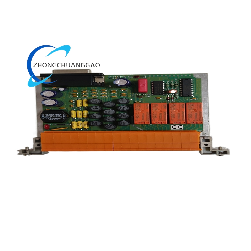
The Honeywell 05704-A-0121 is a dual-function fire alarm notification appliance designed for both audible and visual alerting in commercial, industrial, institutional, and residential fire alarm systems. It integrates a xenon flash tube strobe rated at 75 candela (CD) and a piezoelectric horn/sounder rated at 100 dB SPL into one surface-mount housing. The device is field-selectable between synchronous (strobe and horn activate simultaneously) and alternating (strobe and horn alternate in sequence) operation modes. It complies with NFPA 72: National Fire Alarm and Signaling Code, UL 1971, and EN 54-23 standards.
Description
Technical Specifications:
- Model Number: 05704-A-0121
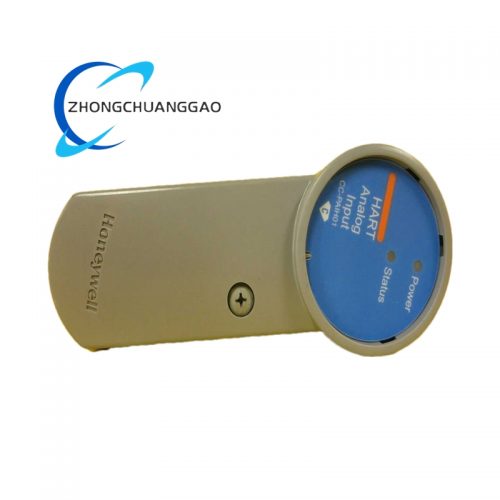
- Manufacturer: Honeywell Fire Safety
- Product Type: Fire Alarm Strobe/Horn Combination Notification Appliance
- Strobe Type: Xenon Flash Tube (360° omnidirectional)
- Strobe Intensity: 75 candela (CD) minimum (at 1 m)
- Sounder Type: Piezoelectric Horn
- Sound Level: 100 dB SPL at 10 feet (3 meters)
- Operating Voltage: 24 VDC (nominal)
- Voltage Range: 16 VDC to 32 VDC
- Current Draw (Alarm): 85 mA typical (strobe + horn simultaneous)
- Current Draw (Standby): <1 mA (supervised)
- Selectable Modes: Synchronous / Alternating
- Mounting Type: Surface-mount with single-gang backbox
- Wiring: Two-wire, polarity-insensitive (Class A or Class B circuits)
Functional Features:
- Dual Alerting: Simultaneous audible (100 dB horn) and visual (75 CD xenon strobe) notification
- Field-Selectable Operation Mode: Switch between synchronous (both activate at same time) and alternating (strobe and horn alternate) via internal DIP switches
- 360° Omnidirectional Strobe: Xenon flash tube provides full-room visual coverage without directional limitation
- Polarity-Insensitive Wiring: Operates correctly regardless of wire polarity; connects to either Class A or Class B signaling line circuits (SLC)
- Two-Wire Operation: Connects to the fire alarm control panel loop using only 2 wires (signal + ground); no separate power supply required
- Supervised Circuit: Internal end-of-line (EOL) resistor provides supervision; open-circuit or short-circuit fault is reported to the fire alarm control panel (FACP)
- Loud Horn Output: 100 dB SPL at 10 feet exceeds NFPA 72 minimum 75 dB requirement for sleep areas and 85 dB for non-sleep areas
- High-Intensity Strobe: 75 CD exceeds NFPA 72 minimum 15 CD requirement for visual notification appliances
- Tamper-Resistant Design: Requires a screwdriver to access internal DIP switches; prevents unauthorized mode changes
Performance Parameters:
| Parameter | Value |
|---|---|
| Model Number | 05704-A-0121 |
| Strobe Intensity | 75 candela (CD) minimum at 1 m |
| Sound Level | 100 dB SPL at 3 m (10 ft) |
| Operating Voltage | 24 VDC (16–32 VDC range) |
| Standby Current | <1 mA |
| Alarm Current | 85 mA typical |
| Operating Temperature | -10°C to +55°C (14°F to 131°F) |
| Storage Temperature | -40°C to +70°C (-40°F to 158°F) |
| Relative Humidity | 5% to 95% (non-condensing) |
| Dimensions (H×W×D) | Approximately 114 × 114 × 63 mm (4.5 × 4.5 × 2.5 in) |
| Weight | Approximately 280 g (0.62 lbs) |
| Mounting | Surface-mount, single-gang backbox (3-13/16 in diameter) |
| Compliance | UL 1971, UL 464, EN 54-23, NFPA 72, CAN/ULC-S524 |
| Listing | UL Listed, FM Approved, CE Marked |
Material Composition:
- Housing: UL 94V-0 rated flame-retardant polycarbonate blend (white, red, or ivory finish options)
- Strobe Lens: Clear polycarbonate dome with UV-stabilized coating for long-term yellowing resistance
- Horn Diaphragm: Piezoelectric ceramic element with brass backing plate
- Internal Reflector: Specular aluminum reflector cup for xenon strobe light optimization
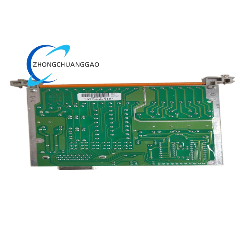
- Circuit Board: FR-4 fiberglass epoxy laminate with conformal coating
- Terminal Blocks: Tin-plated brass screw terminals
- Gasket: Silicone rubber seal for dust and moisture ingress protection (IP24 rated)
- Mounting Gasket: Neoprene rubber gasket for backbox seal
Structural Features:
- Single-Gang Surface-Mount Design: Fits standard single-gang electrical backbox (3-13/16 in / 97 mm diameter)
- Front Panel: White/red/ivory polycarbonate cover with integrated strobe dome and horn grille
- Internal Layout: Xenon flash tube mounted centrally; piezoelectric horn mounted to rear; PCB with DIP switches and terminal block at bottom
- DIP Switch Access: Requires a flathead screwdriver through a tamper-resistant slot on the front cover
- Terminal Block: 2-wire screw terminals (Loop +, Loop −) with wire gauge accommodation for 14–22 AWG
- Backbox Gasket: Neoprene gasket provides IP24 dust and splash protection when installed
- Ventilation Slots: Small ventilation openings on sides for thermal management of xenon flash tube
- Color Options: Available in white, red, and ivory housing finishes per NFPA 72 color-coding requirements
Working Principle:
The Honeywell 05704-A-0121 connects to a 2-wire Class A or Class B Signaling Line Circuit (SLC) from the fire alarm control panel (FACP). In standby mode, the device draws <1 mA and the internal EOL resistor maintains loop supervision. When the FACP sends an alarm signal (24 VDC applied across the loop), the device activates. In synchronous mode, both the xenon flash tube and the piezoelectric horn activate simultaneously: the xenon tube fires a high-intensity flash of 75 CD omnidirectional light, while the piezoelectric element produces a 100 dB SPL tone. In alternating mode, the strobe and horn alternate in sequence (strobe ON → horn ON → strobe ON → horn ON) at a rate of approximately 1 Hz. The internal EOL resistor value changes upon alarm activation, allowing the FACP to distinguish between normal, alarm, and fault conditions (open circuit, short circuit, or device removal). The DIP switches inside the unit set the operating mode (synchronous vs. alternating) and the EOL resistor value.
Advantages and Highlights:
- Dual Alerting in One Device: Eliminates need for separate horn and strobe units; reduces wiring, labor, and cost
- Exceeds NFPA 72 Minimums: 75 CD strobe (vs. 15 CD minimum) and 100 dB horn (vs. 75 dB minimum for sleep areas) provide superior notification coverage
- 360° Omnidirectional Strobe: Xenon flash tube provides uniform visual coverage in all directions; no dead zones
- Two-Wire Installation: Only 2 wires required; compatible with Class A and Class B SLC circuits; no separate power supply needed
- Field-Selectable Mode: Synchronous or alternating operation set via internal DIP switches; no programming software required
- Fully Supervised: Open-circuit, short-circuit, and device-removal faults are all reported to the FACP
- Polarity-Insensitive: Works regardless of wire polarity; reduces installation errors
- Tamper-Resistant: DIP switches require a screwdriver to access; prevents unauthorized changes
- UL 1971 Listed: Meets the most stringent notification appliance standard in North America
- FM Approved: Approved for use in FM Global-insured properties
- CE Marked / EN 54-23 Compliant: Certified for use in European markets
Applicable Industries:
- Commercial Buildings: Office towers, shopping malls, hotels, retail stores
- Healthcare Facilities: Hospitals, nursing homes, clinics, assisted living facilities
- Educational Institutions: Schools, universities, dormitories, libraries
- Industrial Facilities: Factories, warehouses, manufacturing plants
- Residential Buildings: Apartment complexes, condominiums, high-rise residences
- Hospitality: Hotels, resorts, convention centers
- Government Buildings: Courthouses, municipal buildings, military facilities
- Transportation: Airports, train stations, bus terminals
- Religious Institutions: Churches, mosques, temples, synagogues
- Entertainment Venues: Theaters, stadiums, arenas, nightclubs
Model Series:
| Model Number | Description |
|---|---|
| 05704-A-0121 | Strobe/Horn, 75 CD, 100 dB, surface-mount, synchronous/alternating (current model) |
| 05704-A-0111 | Strobe/Horn, 15 CD, 85 dB, surface-mount, synchronous only |
| 05704-A-0131 | Strobe/Horn, 75 CD, 100 dB, surface-mount, synchronous only |
| 05704-A-0221 | Strobe/Horn, 75 CD, 100 dB, flush-mount, synchronous/alternating |
| 05704-A-0321 | Strobe/Horn, 75 CD, 100 dB, ceiling-mount, synchronous/alternating |
| 05704-A-0421 | Strobe/Horn, 75 CD, 100 dB, wall-mount with bracket, synchronous/alternating |
| 05704-B-0121 | Strobe/Horn, 75 CD, 100 dB, surface-mount, synchronous/alternating, red housing |
| 05704-C-0121 | Strobe/Horn, 75 CD, 100 dB, surface-mount, synchronous/alternating, ivory housing |
Installation Requirements:
- Mounting Surface: Standard single-gang electrical backbox (3-13/16 in / 97 mm diameter) with minimum 25 mm (1 in) depth
- Backbox Material: Metal or non-metallic backbox rated for fire alarm applications
- Wire Gauge: Use 14 AWG to 22 AWG stranded copper wire (CL2 or CL3 rated per NEC Article 760)
- Wiring Configuration: Connect to Class A or Class B SLC; polarity does not matter (polarity-insensitive)
- Loop Connection: Connect Loop (+) and Loop (−) terminals to the FACP signaling line circuit; no separate power supply required
- Mounting Height: Install at minimum 80 inches (2032 mm) AFF per NFPA 72 for wall-mount audible/visual appliances in sleep areas; maximum 80 inches (2032 mm) for general areas
- Spacing: Install appliances at maximum 100 feet (30 m) intervals in corridors per NFPA 72
- Grounding: Not required (2-wire, non-grounded circuit); however, backbox must be securely fastened
- Environmental Rating: IP24 when installed with backbox gasket; suitable for indoor use only
- Clearance: Maintain minimum 25 mm (1 in) clearance around the device for ventilation
Usage Precautions:
- Do not exceed 32 VDC supply voltage: Overvoltage will destroy the xenon flash tube and piezoelectric element permanently
- Do not reverse polarity on auxiliary devices: While this device is polarity-insensitive, connected auxiliary devices (relays, solenoids) must have correct polarity
- Do not install in wet or outdoor locations: The device is rated IP24 (indoor only); water ingress will cause circuit failure
- Do not cover the strobe lens: The polycarbonate dome must remain unobstructed for full 360° visual coverage
- Do not paint or modify the housing: Paint covers the strobe lens and reduces light output; voids UL listing
- Do not ignore fault signals: An EOL fault (open circuit, short circuit, or device missing) must be investigated and corrected within 24 hours per NFPA 72
- Test monthly per NFPA 72: Perform functional test of all notification appliances at least once per month; document results
- Do not use for non-fire-alarm purposes: This device is UL 1971 listed for fire alarm use only; unauthorized use voids certification
- Replace every 10 years: Even if functional, the xenon flash tube degrades over time; replace per manufacturer lifecycle recommendation
- Use only UL listed cable: Zone wiring must use CL2 or CL3 rated cable per NEC Article 760; do not use Romex (NM) cable
- Do not install above 55°C (131°F): Exceeding operating temperature range voids warranty and degrades piezoelectric element
- Set DIP switches before installation: Configure synchronous/alternating mode and EOL resistor value before mounting; changing settings requires device removal
- Record all test results: Maintain a log of every monthly test for regulatory compliance (NFPA 72 Chapter 14) and insurance purposes
- Use only Honeywell-specified backbox gasket: The neoprene gasket is required for IP24 rating; do not substitute with other materials
Reviews
There are no reviews yet.