Product Short Description
Product Introduction:
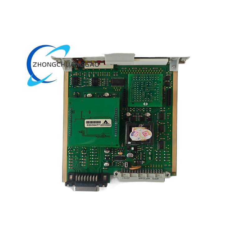
The Honeywell 05701-A-0302 is a DIN-rail mounted, 4-zone, 2-output fire safety control relay manufactured by Honeywell Fire Safety (formerly Potter Electric Signal Company). It serves as the central logic controller for fire alarm interface panels, managing the transition from alarm activation to suppression system discharge. The unit monitors up to 4 independently programmable fire alarm input zones and controls 2 programmable output relays for suppression bottle discharge, damper actuation, fan shutdown, and door release sequences.

Description
Technical Specifications:
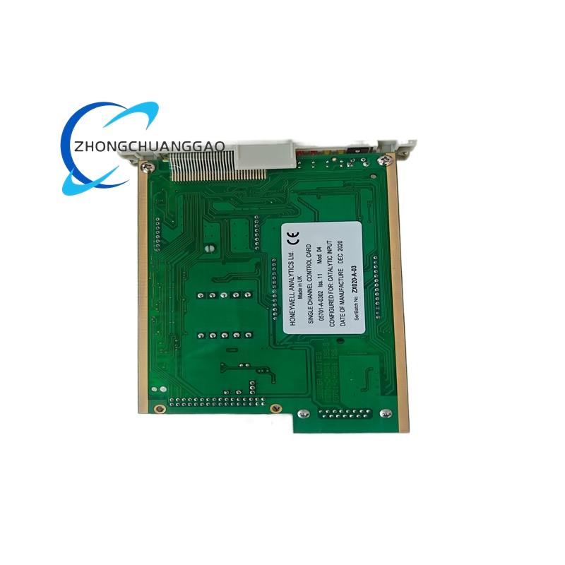
- Model Number: 05701-A-0302
- Manufacturer: Honeywell Fire Safety
- Type: Programmable Fire Safety Control Relay
- Input Zones: 4 programmable zones (Zone 1–4)
- Output Channels: 2 programmable relay outputs (Output A & Output B)
- Supply Voltage: 24 VDC (nominal)
- Operating Voltage Range: 18 VDC to 32 VDC
- Input Type: Dry contact / voltage-free contacts (NO/NC selectable)
- Output Type: Dry contact relays (Form C, changeover)
- Output Rating: 5 A @ 30 VDC resistive / 250 VAC resistive
- Current Consumption: <100 mA at 24 VDC (standby)
- Response Time: <200 ms from zone activation to output change
- Mounting: DIN rail (EN 60715, 35 mm)
Functional Features:
- 4 Independently Programmable Zones: Each zone supports individual delay timers, output assignments, and activation logic
- 2 Programmable Relay Outputs: Outputs can be configured for suppression discharge, HVAC shutdown, fan control, or door release
- Zone Delay Timers: Adjustable delay from 0 to 300 seconds per zone for staged activation
- Output Delay Timers: Adjustable delay from 0 to 300 seconds per output for sequenced discharge
- Zone-to-Output Mapping: Any zone can trigger any output independently or in combination
- Zone Indicators: Individual LED status indicators for each of the 4 zones
- Output Status Indicators: LED indicators for Output A and Output B state
- End-of-Line (EOL) Monitoring: Built-in supervision for input circuit integrity
- Fail-Safe Operation: Loss of power or signal fault defaults to safe state per NFPA requirements
- Audible Alarm: Internal buzzer activates upon zone alarm condition
- Reset Functionality: Manual reset required after alarm condition clears (per NFPA 2001)
Performance Parameters:
| Parameter | Value |
|---|---|
| Supply Voltage | 24 VDC (18–32 VDC range) |
| Standby Current Draw | <100 mA |
| Alarm Current Draw | <150 mA |
| Input Contact Rating | 30 VDC / 1 A (dry contact) |
| Output Contact Rating | 5 A @ 30 VDC / 250 VAC (Form C) |
| Operating Temperature | -10°C to +55°C (14°F to 131°F) |
| Storage Temperature | -40°C to +70°C (-40°F to 158°F) |
| Relative Humidity | 5% to 95% (non-condensing) |
| Response Time | <200 ms |
| Zone Delay Range | 0–300 seconds (adjustable) |
| Output Delay Range | 0–300 seconds (adjustable) |
| Dimensions (W×H×D) | Approximately 90 × 105 × 65 mm (3.54 × 4.13 × 2.56 in) |
| Weight | Approximately 280 g (0.62 lbs) |
Material Composition:
- Housing: UL 94V-0 rated flame-retardant polycarbonate / ABS blend
- Terminal Blocks: Tin-plated brass with screw-clamp connections
- PCB Substrate: FR-4 fiberglass epoxy laminate
- Relay Contacts: Silver-cadmium oxide (AgCdO) alloy for high-reliability switching
- DIN Rail Clip: Zinc-plated steel with spring-loaded retention
- LED Indicators: High-brightness LEDs (red/green) with diffused polycarbonate lenses
- Internal Wiring: 22 AWG stranded copper with PVC insulation
Structural Features:
- DIN Rail Mountable: Snap-on / slide-on mounting to standard 35 mm top-hat rail
- Front Panel Layout: Zone status LEDs (Z1–Z4), output status LEDs (A/B), power LED, test/reset button
- Rear Panel: DIN rail clip, terminal blocks for all 4 zone inputs, 2 output relay terminals, 24 VDC power terminals
- Terminal Configuration: Screw-type terminal blocks rated for 14–22 AWG wire gauge
- Compact Form Factor: Single-module width design fits in standard fire alarm control panels
- Modular Design: No internal user-serviceable components; unit replacement is plug-and-play
Working Principle:
The Honeywell 05701-A-0302 continuously monitors 4 dry-contact input zones connected to fire alarm detection devices (smoke detectors, heat detectors, pull stations, or manual call points). When any zone input closes (alarm condition), the internal microcontroller evaluates the programmed zone-to-output mapping logic. After the configured zone delay timer expires, the corresponding output relay(s) activate. The output relays are Form C (changeover) contacts that switch from normally closed (NC) to normally open (NO) state, sending a 24 VDC signal to the fire suppression system solenoid valve, HVAC shutdown relay, or damper actuator. The output delay timer provides a secondary delay between zone activation and physical output switching. The unit requires a manual reset after the alarm condition clears and all zone inputs return to normal (open) state. The internal EOL supervision circuit monitors each input zone for open-circuit (wire cut) and short-circuit faults, triggering a trouble condition if detected.
Advantages and Highlights:
- NFPA 2001 Compliant: Meets all requirements for clean agent fire suppression system control per NFPA 2001: Standard on Clean Agent Fire Extinguishing Systems
- 4-Zone Flexibility: Supports up to 4 independent fire detection zones with individual programming
- Dual Output Channels: Controls 2 separate systems simultaneously (e.g., suppression + HVAC shutdown)
- Adjustable Delay Timers: 0–300 second range per zone and per output for staged, sequential activation
- Built-In EOL Supervision: Detects open and short circuit faults on all input zones automatically
- Fail-Safe Design: Defaults to safe state on power loss or internal fault
- Audible Alarm: Integrated buzzer provides local alarm indication
- DIN Rail Mounting: Standard industrial mounting for clean panel integration
- No Programming Required for Basic Use: Pre-configured default mapping available; advanced mapping via front-panel DIP switches or jumper settings
- UL Listed: UL 864 listed for fire alarm control unit applications
- FM Approved: FM 2001 approved for use in fire suppression systems
Applicable Industries:
- Data Centers: Clean agent (FM-200, Novec 1230, FE-36) suppression system control
- Telecommunications Facilities: Server room and equipment room fire protection
- Commercial Buildings: Office fire suppression with HVAC interlock
- Healthcare Facilities: Operating rooms, MRI suites, pharmacy clean agent systems
- Museums and Archives: Inert gas suppression for irreplaceable asset protection
- Industrial Control Rooms: Electrical panel and SCADA room fire protection
- Laboratories: Chemical storage and fume hood area suppression
- Banking and Financial Institutions: Vault and server room protection
Model Series:
| Model Number | Description |
|---|---|
| 05701-A-0102 | 2-zone, 1-output fire safety control relay |
| 05701-A-0202 | 2-zone, 2-output fire safety control relay |
| 05701-A-0302 | 4-zone, 2-output fire safety control relay (current model) |
| 05701-A-0402 | 4-zone, 4-output fire safety control relay |
| 05701-A-0602 | 6-zone, 2-output fire safety control relay |
| 05701-A-0802 | 8-zone, 2-output fire safety control relay |
| 05701-B-0302 | 4-zone, 2-output with audible horn variant |
Installation Requirements:
- Mounting Surface: Standard 35 mm DIN rail (EN 60715) in a fire alarm control panel or dedicated enclosure
- Power Supply: 24 VDC regulated, filtered, and supervised per NFPA 72 requirements
- Battery Backup: Required; 24 VDC supply must be on emergency power circuit with minimum 24-hour battery backup
- Wiring Gauge: Use 14 AWG to 22 AWG stranded copper wire for all connections
- Zone Wiring: Connect fire detection devices as normally open (NO) dry contacts; supervised end-of-line resistor required per zone
- Output Wiring: Connect to suppression solenoid valves, HVAC shutdown relays, or damper actuators via Form C relay contacts
- Grounding: Connect enclosure ground to building equipment grounding conductor
- Clearance: Maintain minimum 25 mm (1 inch) clearance above and below unit for ventilation
- Panel Rating: Install in an enclosure rated NEMA 4 / IP65 if located in harsh environments
Usage Precautions:
- Do not exceed 32 VDC supply voltage: Overvoltage will damage internal circuitry permanently
- Do not reverse polarity: 24 VDC supply must be connected with correct polarity; reverse polarity protection is not provided
- Do not bypass EOL resistors: End-of-line supervision resistors are mandatory on every zone; bypassing voids UL/FM listing and NFPA compliance
- Do not ignore trouble signals: EOL fault (open or short circuit) must be investigated and corrected immediately
- Manual reset is mandatory after every alarm: The unit will not automatically re-arm; press reset button only after all zone inputs are confirmed normal
- Test monthly per NFPA 25: Perform functional test of all zones and outputs at least once per month
- Do not operate above 55°C (131°F): Exceeding operating temperature range voids warranty and degrades relay contact life
- Replace relay unit every 10 years: Even if functional, relay contact wear accumulates; replace per manufacturer lifecycle recommendation
- Use only UL listed fire alarm cable: Zone wiring must use CMR or CMP rated cable per NEC Article 760
- Do not cover ventilation openings: The unit requires airflow for thermal management; do not obstruct top or bottom vents
- Record all alarm events: Maintain a log of every zone activation and output discharge for regulatory compliance and insurance purposes
-500x500.jpg)
Reviews
There are no reviews yet.