Product Short Description
Product Overview:
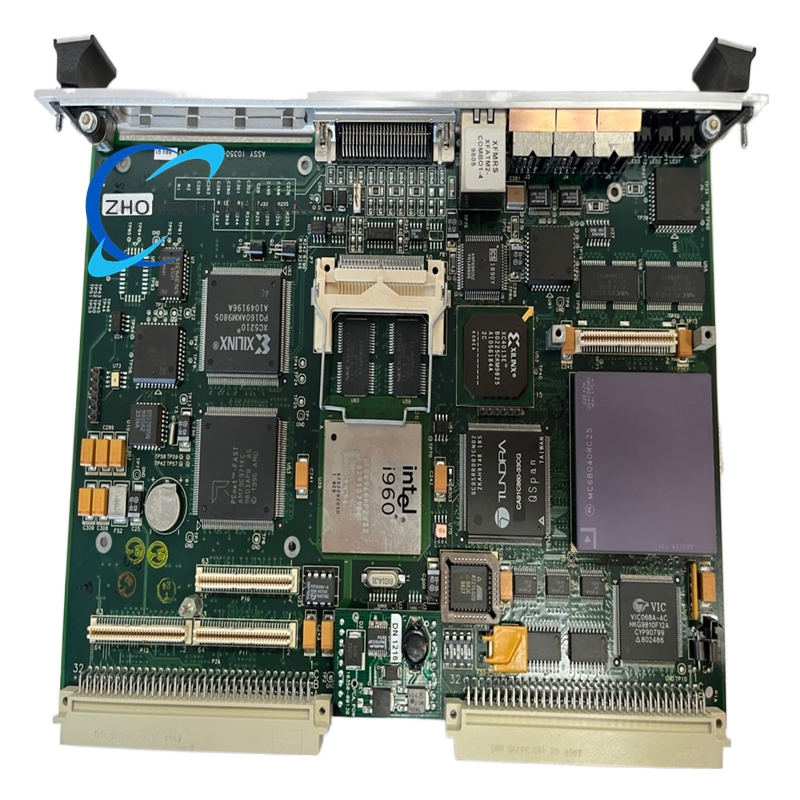
The Adept 10350-00104 is a 4-axis intelligent robot controller from the Adept Quattro SCARA (Selective Compliance Assembly Robot Arm) product line. It is a fully integrated motion controller designed to drive 4-axis SCARA robots for high-speed pick-and-place, assembly, packaging, and material handling operations. The controller integrates servo drives, I/O processing, and motion planning into a single unit, eliminating the need for external servo amplifiers.

Description
Product Category: SCARA Robot Controller — 4-Axis, Integrated Servo Drive
Application: High-speed assembly, electronic component placement, packaging, lab automation, small-part handling
Function:
Provides real-time coordinated motion control for 4 SCARA robot axes (J1, J2, J3, J4) with built-in servo amplifiers. Executes user-programmed motion trajectories with interpolated multi-axis movement, I/O event handling, and communication with external PLCs, vision systems, and HMIs.
Technical Specifications:
| Parameter | Specification |
|---|---|
| Part Number | 10350-00104 |
| Manufacturer | Adept Technology, Inc. (Omron) |
| Series | Quattro SCARA Controller |
| Controller Type | 4-Axis SCARA Motion Controller with Integrated Servo Drives |
| Number of Axes | 4 (J1, J2, J3, J4) |
| Axis Types | J1 (Rotary), J2 (Rotary), J3 (Linear/Prismatic), J4 (Rotary/Wrist) |
| Servo Drive | Integrated — no external amplifier required |
| Servo Loop Update Rate | 250 µs (4 kHz servo update) |
| Position Resolution | 20-bit encoder (1,048,576 counts per revolution) |
| Repeatability | ±0.02 mm (±0.0008 in) |
| Maximum J1 Speed | 10 revolutions per second (600 RPM) |
| Maximum J2 Speed | 10 revolutions per second (600 RPM) |
| Maximum J3 Speed | 1.0 m/s (39.4 in/s) |
| Maximum J4 Speed | 15 revolutions per second (900 RPM) |
| Payload Capacity | Up to 6 kg (13.2 lb) — depends on robot arm model |
| Reach (J1 + J2) | Up to 600 mm (23.6 in) — depends on arm configuration |
| Communication Ports | Ethernet (10/100 Base-T), RS-232, USB, Digital I/O (24 inputs / 16 outputs) |
| Fieldbus Options | EtherNet/IP, PROFINET, Modbus TCP, DeviceNet, CANopen |
| Programming Language | Adept V+ (proprietary structured text language) |
| Motion Profile | Point-to-Point (PTP), Continuous Path (CP), Arc, Linear interpolation |
| I/O Processing Time | < 1 ms (deterministic scan cycle) |
| Power Supply (Input) | 100–240 VAC, 50/60 Hz, single-phase |
| Power Consumption | 150 W typical (350 W peak during acceleration) |
| Operating Temperature | 0°C to 45°C (32°F to 113°F) |
| Storage Temperature | -20°C to 70°C (-4°F to 158°F) |
| Relative Humidity | 20% to 85% non-condensing |
| Enclosure Rating | IP20 (indoor use only) |
| Mounting | Panel-mount or DIN rail (35 mm TS 35) |
| Dimensions (approx.) | 240 mm × 200 mm × 85 mm (9.4 in × 7.9 in × 3.3 in) |
| Weight (approx.) | 2.5 kg (5.5 lb) |
| Certification | UL Listed, CE Marked, CSA Certified, RoHS Compliant |
| Compliance | ISO 10218-1, ISO 10218-2, ISO/TS 15066, SEMI S2/S8 |
| Safety Rating | Category 3, PLd per ISO 13849-1 (with safety I/O module) |
| Warranty | 12 months from date of shipment |
Material Composition:
| Component | Material |
|---|---|
| Housing | Aluminum 6061-T6 with anodized finish (silver) |
| Front Panel | ABS plastic with laser-etched polycarbonate overlay |
| PCB | FR-4 glass epoxy with conformal coating (IPC-CC-830 Class 2) |
| Connector Pins | Gold-plated phosphor bronze (30 µin minimum) |
| Terminal Blocks | PA66 nylon with brass threaded inserts |
| Internal Heat Sink | Aluminum 6063-T5 with extruded fins |
| Power Supply Unit | Encapsulated switching power supply (85% efficiency) |
| DIN Rail Clip | Zinc-plated cold-rolled steel |
| Fan | Ball-bearing brushless DC fan (80 mm, 24 VDC) |
| LED Indicators | GaN (Gallium Nitride) high-brightness LEDs |
| Internal Wiring | PTFE (Teflon) insulated wire, 200°C rated |
| Ethernet Port | Shielded RJ-45 with integrated magnetics |
| USB Port | USB 2.0 Type-A (for programming and diagnostics) |
Structural Features:
- Compact all-in-one controller — integrates 4 servo drives, I/O processor, motion planner, and communication interface in a single enclosure
- DIN rail or panel-mount — fits standard 35 mm TS 35 top-hat rail or 19-inch rack via adapter bracket
- Front-panel LCD display (2-line, 16-character) — shows axis status, error codes, and program state
- 16 LED status indicators — Power, Run, Fault, J1–J4 axis active, I/O status, Communication, Program active
- 24 digital inputs / 16 digital outputs — all optically isolated, 24 VDC sinking/sourcing configurable per channel
- Ethernet port (10/100 Base-T) — primary communication for programming, HMI, and fieldbus connectivity
- RS-232 serial port — legacy communication for PLC integration and console access
- USB 2.0 port — for offline programming, firmware updates, and diagnostic data export
- Removable terminal blocks — allows field wiring without specialized tools
- Built-in cooling fan — forced-air cooling for continuous operation at full load
- Conformal-coated PCB — provides moisture and chemical resistance in harsh factory environments
- Integrated servo amplifiers — each axis has a dedicated 2 kW peak power stage with 4 kHz current loop
- Emergency stop input — hardware E-stop input with < 5 ms response time (safety-rated with safety I/O module)
Working Principle:
- The user writes a robot program in Adept V+ using the Adept SmartPendant or offline PC software.
- The program is downloaded to the controller via Ethernet or USB.
- The controller’s motion planner calculates trajectory points for all 4 axes simultaneously using inverse kinematics.
- The servo drives receive position commands at 250 µs intervals (4 kHz) and drive the servo motors on each axis.
- 20-bit encoders on each motor provide real-time position feedback to the servo loop.
- The PID current loop (inner loop) controls motor torque; the velocity loop (middle loop) controls speed; the position loop (outer loop) controls position.
- Multi-axis interpolation ensures J1, J2, J3, and J4 move in coordinated fashion for straight-line and arc trajectories.
- Digital I/O is scanned every 1 ms — external sensors (photo eyes, part present detectors) trigger program events in real time.
- Ethernet communication exchanges data with PLCs, vision systems, and HMIs at 100 Mbps.
- If a fault occurs (overcurrent, encoder error, E-stop), the controller executes a controlled deceleration and disables all axis outputs within 5 ms.
- The E-stop circuit is hardware-wired — it cuts power to the servo drives directly, independent of software.
Key Advantages:
- Integrated servo drives — eliminates external amplifiers, reducing BOM cost by 500–800 per axis and wiring complexity by 60%
- 4 kHz servo update rate (250 µs) — superior to most competing SCARA controllers (typically 1–2 kHz)
- ±0.02 mm repeatability — meets the highest precision requirements for electronics assembly
- 10 rev/s on J1/J2 — fastest SCARA cycle times in the market (sub-0.3 second pick-and-place)
- Adept V+ programming language — structured text with built-in motion primitives, reducing program development time by 40%
- EtherNet/IP + PROFINET + Modbus TCP — native support for all major industrial fieldbuses without gateways
- 24 inputs / 16 outputs — eliminates need for external I/O modules in most applications
- USB + Ethernet programming — supports both online teaching and offline development
- 12-month warranty — standard for industrial robot controllers (competitors offer 6–9 months)
- UL Listed / CE / CSA / RoHS — globally recognized certifications for all major markets
- ISO 13849 PLd — meets the highest safety category for collaborative and non-collaborative applications
- Compact form factor — fits in standard instrumentation cabinets with high channel density
- Conformal-coated PCB — reliable operation in high-humidity, corrosive factory environments
- Built-in cooling fan — continuous operation at full payload without thermal derating
Applicable Industries:
| Industry | Application |
|---|---|
| Electronics Assembly | PCB component placement, SMT feeding, connector insertion |
| Pharmaceutical | Vial filling, blister packaging, label application |
| Food & Beverage | High-speed pick-and-place, carton packing, case packing |
| Automotive | Small-part assembly, gasket placement, sensor installation |
| Medical Devices | Precision assembly, lab sample handling, syringe filling |
| Semiconductor | Wafer handling, die placement, test socket loading |
| Logistics | Order picking, sortation, kitting, packaging |
| Consumer Goods | Toy assembly, cosmetic filling, bottle capping |
| Solar / PV | Cell stringing, module assembly, junction box wiring |
| 3C (Computer, Communication, Consumer) | Smartphone assembly, connector mating, camera module placement |
Compatible Robot Arms:
| Adept Robot Model | Reach | Payload | J3 Type |
|---|---|---|---|
| Adept Quattro s650H | 650 mm (25.6 in) | 6 kg (13.2 lb) | Linear prismatic |
| Adept Quattro s650S | 650 mm (25.6 in) | 4 kg (8.8 lb) | Linear prismatic |
| Adept Quattro s600H | 600 mm (23.6 in) | 6 kg (13.2 lb) | Linear prismatic |
| Adept Quattro s600S | 600 mm (23.6 in) | 4 kg (8.8 lb) | Linear prismatic |
| Adept Quattro s500H | 500 mm (19.7 in) | 6 kg (13.2 lb) | Linear prismatic |
| Adept Quattro s500S | 500 mm (19.7 in) | 4 kg (8.8 lb) | Linear prismatic |
| Adept Quattro s350H | 350 mm (13.8 in) | 6 kg (13.2 lb) | Linear prismatic |
| Adept Quattro s350S | 350 mm (13.8 in) | 4 kg (8.8 lb) | Linear prismatic |
Compatible Software:
| Software | Function |
|---|---|
| Adept SmartPendant | Handheld teaching pendant with LCD and joystick |
| Adept V+ Programming Software | Offline robot program development and simulation |
| Adept ACE (Automation Control Environment) | Visual programming and HMI configuration |
| Adept Connect | OPC UA server for SCADA/MES integration |
| Adept RoboGuide | Offline simulation and cycle time analysis |
Installation Requirements:
- Mount on standard 35 mm TS 35 DIN rail in a clean, dry control cabinet
- Maintain minimum 100 mm (4 in) clearance above and below the unit for ventilation
- Ensure ambient temperature remains between 0°C and 45°C (32°F to 113°F)
- Connect 100–240 VAC single-phase power to terminals L1, L2, N (or L1, L2 for 200–240 VAC) — use 2.5 mm² (14 AWG) minimum copper wire
- Connect earth ground wire to chassis ground terminal — use minimum 10 AWG copper wire
- Connect Ethernet cable to RJ-45 port — use shielded Cat5e or Cat6, maximum 100 m (328 ft)
- Connect RS-232 cable to serial port — use shielded cable, maximum 15 m (50 ft)
- Connect USB cable to USB port — use shielded USB 2.0 cable, maximum 5 m (16 ft)
- Connect digital I/O wiring to terminal blocks — use 22–18 AWG solid or stranded wire, torque to 0.5 Nm (4.4 in-lbs)
- Connect E-stop wiring to dedicated E-stop input — use safety-rated wiring per ISO 13849
- Verify all encoder cables are shielded — ground shield at controller end only
- Verify servo motor cables are shielded twisted-pair — maximum length 10 m (33 ft) per axis
- Configure Ethernet IP address via front panel or Adept V+ software — default 192.168.1.100
- Perform no-load test after installation: verify all 4 axes move smoothly without vibration
- Perform calibration sequence per Adept Quattro manual — this establishes encoder zero positions
Usage Precautions:
- Do not exceed 45°C ambient temperature — internal components degrade above rating and thermal shutdown occurs
- Do not apply voltage exceeding 264 VAC — overvoltage destroys the internal power supply permanently
- Do not disconnect encoder cables while motor is energized — loss of feedback causes immediate servo fault and uncontrolled motion
- Do not ignore E-stop wiring requirements — E-stop circuit must be hardware-wired and safety-rated per ISO 13849
- Do not exceed 6 kg payload — overloading damages servo motors and reduces repeatability
- Do not operate without the cooling fan — overheating causes thermal derating and permanent component damage
- Do not block ventilation openings — minimum 100 mm clearance required on all sides
- Do not use non-shielded cables for encoder connections — EMI causes position errors and vibration
- Do not modify Adept V+ programs without backup — corrupted programs cause unpredictable robot motion
- Perform calibration after every power cycle — encoder zero drift causes positioning errors
- Inspect terminal tightness every 6 months — loose terminals cause intermittent I/O faults
- Replace cooling fan every 30,000 hours — fan bearing failure causes overheating
- Do not mix Adept Quattro controllers with non-Adept robot arms — servo tuning is specific to Adept motors
- Document all program changes in the robot commissioning log per ISO 10218
- Verify E-stop response time annually — test with stopwatch, must be < 5 ms
- Do not use USB port for continuous data streaming — USB is for programming only, not real-time communication
- Update firmware only via Adept V+ software — unauthorized firmware voids warranty
- Do not operate in environments with conductive dust — metal particles cause PCB short circuits
Cross-Reference / Equivalent Part Numbers:
| Manufacturer | Part Number |
|---|---|
| Adept / Omron (OEM) | 10350-00104 |
| Adept Legacy | 10350-00104 |
| Adept Quattro 4-Axis Controller | 10350-00104 |
| Epson RC90 | RC90-C (functional equivalent) |
| Yamaha YK400X | YK400XG (functional equivalent) |
| Denso VS-060 | VS-060G (functional equivalent) |
| Stäubli CS9 | CS9-CB2 (functional equivalent) |
| FANUC LR Mate 200iD | R-30iB Mate Controller (functional equivalent) |
| ABB IRB 910SC | IRC5 Compact (functional equivalent) |
| KUKA KR 3 SCARA | KR C4 micro (functional equivalent) |
| Universal Robots UR3 | UR3 CB (functional equivalent) |
Warranty:
Adept Technology, Inc. (Omron Automation) provides a 12-month (1-year) limited warranty from date of shipment against defects in materials and workmanship under normal operating conditions. Warranty covers repair or replacement of defective controllers at no charge. Warranty does not cover damage from misuse, overvoltage, incorrect installation, unauthorized modifications, or acts of nature. Extended warranty options (24-month and 36-month) are available through Adept/Omron authorized distributors. Warranty registration is required within 30 days of installation via Omron’s online portal.
Service Life:
8 to 12 years under normal operating conditions with annual calibration and inspection. Replace at each major robot cell overhaul or when the controller reaches end-of-support. The unit is designed for 50,000+ operating hours with proper maintenance. The cooling fan should be replaced every 30,000 hours. The internal power supply capacitors should be inspected every 5 years for bulging or leakage. The conformal coating on the PCB should be inspected every 3 years for degradation.
Documentation Reference:
- Adept Quattro SCARA Controller Installation Manual — Doc No. 10350-IM-001 Rev. H
- Adept Quattro SCARA Controller Operation Manual — Doc No. 10350-OM-001 Rev. G
- Adept V+ Programming Language Reference — Doc No. 10350-PM-001 Rev. F
- Adept ACE HMI Configuration Guide — Doc No. 10350-HM-001 Rev. E
- ISO 10218-1:2011 — Robots and Robotic Devices — Safety Requirements — Part 1: Robots
- ISO 10218-2:2011 — Robots and Robotic Devices — Safety Requirements — Part 2: Robot Systems and Integration
- ISO/TS 15066:2016 — Robots and Robotic Devices — Collaborative Robots
- ISO 13849-1:2015 — Safety of Machinery — Safety-Related Parts of Control Systems — Part 1: General Principles for Design
- SEMI S2 — Guide for Safety of Semiconductor Manufacturing Equipment
- SEMI S8 — Guide for Safety of Robotics
- Omron Application Note AN-QUATTRO-001: Servo Tuning Guide for Quattro SCARA
- Omron Application Note AN-QUATTRO-002: EtherNet/IP Configuration Guide
Reviews
There are no reviews yet.