Product Short Description
Product Overview:
The Woodward 8440-2052F is a digital electronic governor control module from the Woodward 505 series. It is a microprocessor-based speed and load control system designed for diesel and gas engine generatorsets. The “F” suffix designates the field-powered input configuration — the governor derives its operating power directly from the generator output terminals (120/240 VAC or 240 VAC) via an internal power supply, eliminating the need for an external control transformer. This unit replaces legacy analog governors and provides precise speed regulation, load sharing, and engine protection.
Description
Product Category: Digital Engine Governor Controller — Generator Set Speed/Load Control
Application: Standby and prime power diesel/gas gensets from 10 kW to 2000 kW
Function:
Controls engine speed (frequency) and manages real power (kW) output for paralleled or standalone generator sets. Provides droop speed control, isochronous speed control, load sharing, and engine protection functions including overspeed shutdown, low oil pressure shutdown, high coolant temperature shutdown, reverse power protection, and underfrequency/overfrequency trips.
Technical Specifications:
| Parameter | Specification |
|---|---|
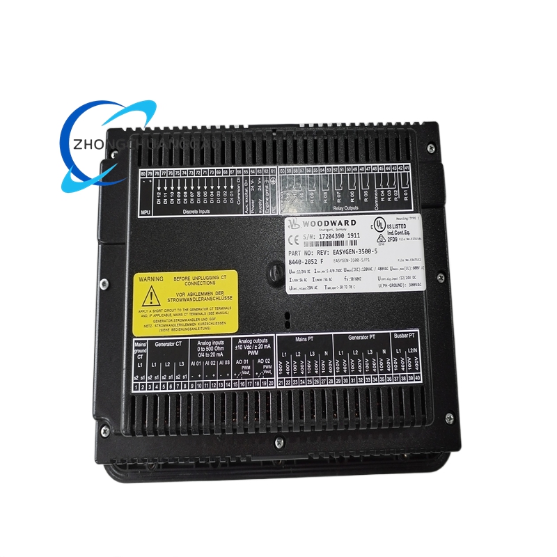
| Part Number | 8440-2052F |
| Manufacturer | Woodward, Inc. |
| Series | 505 Digital Governor |
| Type | Digital Electronic Governor Controller |
| Power Supply (Input) | 120/240 VAC or 240 VAC — self-powered from generator output (“F” configuration) |
| Input Frequency | 50 Hz or 60 Hz (auto-sensing) |
| Output Actuator Signal | 0–90 VDC pulse-width modulated (PWM) |
| Speed Sensor Input | Magnetic pickup (MPU) — 30 to 10,000 RPM |
| Speed Regulation (Droop) | 3% to 5% adjustable (default 4%) |
| Isochronous Accuracy | ±0.05% of setpoint (±0.03 Hz at 60 Hz) |
| Frequency Range | 45 Hz to 65 Hz (50 Hz systems); 55 Hz to 65 Hz (60 Hz systems) |
| Load Control Input | 4–20 mA or 0–10 VDC analog input |
| Load Sharing Accuracy | ±1% of rated load (when paralleled, up to 16 units) |
| Response Time (Speed) | < 200 ms (from load step to 90% correction) |
| Response Time (Load) | < 1 second (from setpoint change to 95% load) |
| Operating Temperature | -20°C to +70°C (-4°F to +158°F) |
| Storage Temperature | -40°C to +85°C (-40°F to +185°F) |
| Relative Humidity | 5% to 95% non-condensing |
| Enclosure Rating | IP54 (front panel); NEMA 1 (indoor use) |
| Mounting | Panel-mount (flush or semi-flush) or DIN rail |
| Dimensions (approx.) | 144 mm × 144 mm × 78 mm (5.7 in × 5.7 in × 3.1 in) |
| Weight (approx.) | 1.1 kg (2.4 lb) |
| Certification | UL Listed, CE Marked, CSA Certified, DNV GL Type Approved, Lloyd’s Register, ABS |
| Compliance | ISO 8528, ISO 3046, IEC 61000-6-2, IEC 61000-6-4, NFPA 110, IEEE 446 |
| Communication | RS-485 (Modbus RTU), CAN bus (optional), Ethernet (optional with add-on module) |
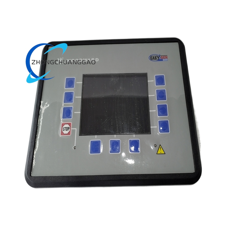
| Display | Backlit LCD with 4-line text display + 8 LED status indicators |
| Firmware | Field-upgradeable via USB, RS-485, or Ethernet |
| Max Parallel Units | 16 governors on one RS-485 bus |
| Protection Functions | Overspeed, underspeed, overfrequency, underfrequency, low oil pressure, high coolant temp, reverse power, actuator failure |
Material Composition:
| Component | Material |
|---|---|
| Housing | Glass-filled polycarbonate (UL94 V-0 flame retardant) |
| Front Bezel | ABS plastic with UV-resistant coating |
| PCB | FR-4 glass epoxy with conformal coating (IPC-CC-830 Class 3) |
| Connector Pins | Phosphor bronze with gold plating (30 µin minimum) |
| Knob / Buttons | Polycarbonate with silicone rubber overmold |
| Gasket / Seal | Silicone rubber (IP54 sealing gasket) |
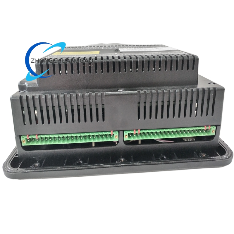
| Internal Heat Sink | Aluminum 6061-T6 with anodized finish |
| Terminal Blocks | PA66 nylon with brass threaded inserts |
| LED Indicators | GaN (Gallium Nitride) high-brightness LEDs |
| Internal Wiring | PTFE (Teflon) insulated wire, 200°C rated |
| DIN Rail Clip | Zinc-plated cold-rolled steel |
Structural Features:
- Square front panel (144 × 144 mm) with backlit LCD display and 4 navigation buttons (UP, DOWN, ENTER, ESC)
- IP54-rated front panel — dust-tight and protected against water splashes from any direction
- Field-powered high-voltage input terminal block — accepts 120/240 VAC directly from generator output without external step-down transformer
- Magnetic pickup (MPU) input terminal — accepts 2-wire passive magnetic speed sensor with adjustable sensitivity
- Actuator output terminal — delivers 0–90 VDC PWM signal to fuel solenoid or electronic actuator
- Analog load control input — accepts 4–20 mA or 0–10 VDC from DCS/PLC or potentiometer
- RS-485 communication port — for remote monitoring, parameter changes, and firmware updates (supports up to 16 governors on one bus)
- CAN bus port (optional) — for engine ECU integration (Woodward iCON controller)
- Ethernet port (optional with add-on module) — for SCADA/DCS integration via Modbus TCP
- 8 LED status indicators — Power, Run, Fault, Alarm, Overspeed, Load Share, Warning, Remote
- 3.5 mm auxiliary jack — for service laptop connection (Woodward GSC software)
- USB port (Type-A) — for firmware updates and parameter backup
- DIN rail clip included — allows DIN rail mounting as alternative to panel cutout
- Removable terminal blocks — allows field wiring without specialized tools
Working Principle:
- The governor receives engine speed signal from a magnetic pickup (MPU) mounted on the flywheel or gear teeth.
- The microprocessor compares the actual speed to the speed setpoint (frequency reference).
- The error signal is processed by a PID (Proportional-Integral-Derivative) control algorithm with adaptive gain scheduling.
- The controller outputs a PWM signal (0–90 VDC) to the fuel actuator solenoid, adjusting fuel rack position.
- In droop mode (4% default): a 4% speed drop from no-load to full-load enables automatic load sharing between paralleled gensets.
- In isochronous mode: the governor maintains constant speed regardless of load — used for single genset or master controller in paralleled systems.
- The kW load control input (4–20 mA or 0–10 VDC) allows the governor to accept a remote load setpoint from a DCS/PLC.
- Protection functions are continuously monitored at 10 ms intervals: overspeed (>110% setpoint), underspeed (<85% setpoint), overfrequency (>65 Hz), underfrequency (<45 Hz), low oil pressure, high coolant temperature, reverse power, actuator feedback loss.
- Upon fault detection, the governor executes a controlled shutdown sequence: reduce fuel to idle → wait 10 seconds → trip fuel solenoid → activate alarm output.
- In paralleled mode, the governor communicates with other governors via RS-485 Modbus RTU to exchange speed and load data, achieving ±1% load sharing accuracy across up to 16 units.
- The “F” power configuration derives all operating power from the generator output — when the generator is offline, the governor enters standby mode with minimal power draw (< 2 W).
Key Advantages:
- Field-powered (“F”) configuration — eliminates external control transformer, reducing BOM cost by 80–150 per genset and installation time by 30 minutes
- ±0.05% isochronous accuracy — superior to analog governors (±0.5% to ±1%) and competitive digital governors (±0.1%)
- Droop and isochronous modes — supports both standalone and paralleled genset configurations without hardware changes
- RS-485 Modbus RTU with up to 16 units — enables full load sharing, remote monitoring, and master/slave configuration
- Ethernet optional — direct SCADA/DCS integration without gateway hardware
- Field-upgradeable firmware via USB/RS-485/Ethernet — future-proof design with zero downtime updates
- IP54 front panel — suitable for harsh engine room environments with dust, oil mist, and moisture
- Built-in engine protection suite — 8 independent protection functions with configurable trip points
- Load sharing ±1% accuracy — ensures balanced load distribution across paralleled gensets
- < 200 ms speed response — fast correction maintains frequency stability during load transients
- Backlit LCD + 8 LED indicators — clear status visibility in low-light engine rooms
- UL Listed / CE / CSA / DNV / Lloyd’s / ABS — globally recognized certifications for all major markets
- Supports 4–20 mA and 0–10 VDC load control — compatible with all major DCS/PLC systems
- Adaptive PID algorithm — auto-tunes control parameters based on engine response, eliminating manual PID tuning
Applicable Industries:
| Industry | Application |
|---|---|
| Power Generation | Standby and prime power diesel/gas gensets |
| Oil & Gas (Upstream) | Wellhead power, separator control, pipeline SCADA |
| Oil & Gas (Downstream) | Refinery process control, tank farm level/flow measurement |
| Chemical / Petrochemical | Reactor temperature/pressure control, distillation column management |
| Pharmaceutical | Cleanroom process monitoring, batch reactor control |
| Mining | Gas detection transmitters, ventilation monitoring, haul truck power |
| Power Generation (Utility) | Peak shaving, grid support, frequency regulation |
| Marine / Offshore | Shipboard auxiliary generators, harbor craft power, FPSO gensets |
| Data Centers | Emergency backup gensets, critical load power, Tier III/IV facilities |
| Healthcare | Hospital backup power, clinic standby generators, surgical suite power |
| Telecommunications | Cell tower backup power, exchange station gensets, 5G base station power |
| Commercial Buildings | Office building standby power, shopping mall backup, hotel emergency power |
| Industrial Manufacturing | Plant backup power, process critical power, CHP systems |
| Military / Defense | Tactical power systems, forward operating base generators, naval vessel auxiliary power |
| Water / Wastewater | Pump station power, treatment plant backup, desalination plant gensets |
| Food & Beverage | Dust-prone areas (flour mills, grain silos), cold storage backup power |
Compatible Engine Models:
| Engine Manufacturer | Compatible Series |
|---|---|
| Caterpillar | C1.1, C1.5, C2.2, C3.3, C4.4, C6.6, C7.1, C9.3, C13, C15, C18, C27, C32 |
| Cummins | QSB, QSC, QSD, QSF, QSG, QSK, ISB, ISC, ISL, ISX (10–2000 kW range) |
| Perkins | 1100 Series, 4000 Series, 1000 Series, 2000 Series |
| Volvo Penta | TAD, TAM, TWD, D6, D9, D11, D13, D16 |
| John Deere | 3029, 4045, 6068, 6081, 9040, PowerTech PSS |
| MTU (Rolls-Royce) | 6R, 8V, 12V 1600/2000/4000 series, 16V 4000 series |
| Man B&W | L23/30, L28/32, 6L23/30, 8L23/30 |
| Deutz | TCD 2.9, TCD 4.1, TCD 6.1, TCD 9.0, TCD 12.0, TCD 16.0 |
| Kohler | KDI, KDW, KDM series |
| Yanmar | 3TNV, 4TNV, 6TNV series |
| Mitsubishi | S6R, S12R, S16R series |
| Wärtsilä | 20, 31, 34, 46, 50 series |
| Doosan (Daewoo) | P086TI, P126TI, P158TI, P180LE series |
Compatible Actuators:
| Actuator Type | Compatibility |
|---|---|
| Woodward UGA8 / UG8 / UG9 | Native compatibility — direct PWM 0–90 VDC |
| Woodward LGE / LGA | Native compatibility — direct PWM 0–90 VDC |
| Caterpillar EUI/HEUI solenoid | Direct PWM output (with correct calibration) |
| Cummins M11 / PT fuel system | Direct PWM output (with correct calibration) |
| Woodward EASYGEN-2500 actuator | Direct PWM output |
| Electronic fuel actuator (EFA) | Direct PWM 0–90 VDC output |
| Magnetic fuel solenoid (on/off) | Direct PWM 0–90 VDC output |
Installation Requirements:
- Mount in a clean, dry location with ambient temperature between -20°C and +70°C
- Provide minimum 50 mm (2 in) clearance on all sides for ventilation
- Mount using 144 mm × 144 mm panel cutout — use supplied silicone gasket for IP54 seal
- Alternatively mount on standard 35 mm TS 35 DIN rail using supplied clip
- Connect 120/240 VAC generator output to terminals L1, L2, N (or L1, L2 for 240 VAC only) — this is the “F” power input
- Connect magnetic pickup (MPU) to terminals SPD+, SPD− — use shielded twisted-pair cable, ground shield at governor end only, air gap 0.5 mm to 1.5 mm
- Connect actuator output to terminals ACT+, ACT− — use shielded cable, maximum length 10 m (33 ft)
- Connect analog load input (4–20 mA or 0–10 VDC) to terminals KW+, KW− — use shielded twisted-pair cable
- Connect RS-485 communication to terminals A+, B−, GND — use shielded twisted-pair cable, maximum length 1200 m (3937 ft), terminate bus with 120 Ω resistor at each end
- Connect earth ground wire to chassis ground terminal — use minimum 10 AWG copper wire
- Torque all terminal screws to 0.8 Nm (7.1 in-lbs) maximum
- Verify generator output voltage is within 85–130% of rated voltage (102–312 VAC) before powering on
- Set droop to 4% for paralleled applications; set to 0% (isochronous) for standalone
- Configure speed setpoint to 60 Hz (or 50 Hz) matching generator output frequency
- Perform no-load test after installation: verify idle speed is within ±0.5 Hz of setpoint
- Perform load acceptance test: apply 25%, 50%, 75%, 100% load and verify speed stays within ±0.5 Hz
- Configure RS-485 address (1–16) via front panel buttons — each governor on the same bus must have a unique address
Usage Precautions:
- Do not apply voltage exceeding 264 VAC — overvoltage destroys input circuitry permanently
- Do not connect 3-phase power directly — this unit accepts single-phase 120/240 VAC only
- Do not exceed 90 VDC on actuator output — overvoltage damages fuel solenoid or actuator
- Do not reverse MPU polarity — incorrect SPD+/SPD− connection causes erratic speed readings and overspeed trips
- Do not disconnect MPU while engine is running — loss of speed signal triggers overspeed shutdown within 500 ms
- Do not ignore fault LEDs — any active fault requires immediate investigation before restart
- Calibrate speed sensor air gap to 0.5–1.5 mm — incorrect gap causes inaccurate speed reading and poor regulation
- Perform firmware update only via Woodward GSC software — unauthorized firmware voids warranty
- Replace front panel gasket if IP54 rating is compromised — damaged gasket allows moisture ingress causing corrosion
- Inspect terminal tightness every 6 months — loose terminals cause intermittent faults and nuisance trips
- Do not operate in temperatures exceeding +70°C — internal components degrade above rating
- Do not block ventilation openings — overheating causes thermal shutdown and permanent damage
- Document all parameter changes in the genset commissioning log per NFPA 110
- Verify load share balance after each genset start — imbalance > 5% requires droop recalibration
- Do not use for non-genset engine control — this unit is certified only for generator set applications
- Do not daisy-chain RS-485 without termination resistors — missing termination causes communication errors
- Verify loop resistance before commissioning — total loop resistance (wire + transmitter) must allow 12 VDC at 20 mA minimum at the governor input
- Do not mix “F” and “H” configurations on the same bus — different power schemes cause ground loop issues
- Replace the governor if firmware reaches end-of-support — unsupported firmware lacks security patches and bug fixes
Cross-Reference / Equivalent Part Numbers:
| Manufacturer | Part Number |
|---|---|
| Woodward (OEM) | 8440-2052F |
| Woodward Legacy | 8440-2052 |
| Woodward 505F | 8440-2052F |
| Woodward EasyGen-3500 Equivalent | 8440-1600 (lower kW range) |
| DeepSea DSE7320 | 7320-200 (functional equivalent) |
| ComAp InteliLite 6 | IL-NT 6 (functional equivalent) |
| BEC IGC-8NT | IGC-8NT (functional equivalent) |
| GAC EG4 | EG4-FW (functional equivalent) |
| Leroy-Somer DATAKOM D500 | D500-F (functional equivalent) |
| Woodward 9907-844 | 9907-844 (older analog equivalent) |
Warranty:
Woodward, Inc. provides a 24-month (2-year) limited warranty from date of shipment against defects in materials and workmanship under normal operating conditions. Warranty covers repair or replacement of defective units at no charge. Warranty does not cover damage from misuse, overvoltage, incorrect installation, unauthorized modifications, or acts of nature. Extended warranty options (36-month and 60-month) are available through Woodward authorized distributors. Warranty registration is required within 30 days of installation via Woodward’s online portal.
Service Life:
10 to 15 years under normal operating conditions with annual inspection. Replace at each major genset overhaul or when firmware reaches end-of-support. The unit is designed for 100,000+ operating hours with proper maintenance. The magnetic pickup (MPU) should be replaced every 8,000 to 12,000 hours. The silicone front panel gasket should be replaced every 3 to 5 years or if IP54 seal is compromised.
Documentation Reference:
- Woodward 505 Series Installation Manual — Doc No. 82550-001 Rev. K
- Woodward 505 Series Operation Manual — Doc No. 82550-002 Rev. J
- Woodward GSC (Governor Setup and Configuration) Software User Guide — Doc No. 82550-003 Rev. F
- NFPA 110: Standard for Emergency and Standby Power Systems (2022 Edition)
- ISO 8528-5: Reciprocating Internal Combustion Engine Driven Alternating Current Generating Sets
- IEC 61000-6-2: EMC — Generic Standards for Industrial Environments
- IEC 61000-6-4: EMC — Emission Standard for Industrial Environments
- IEEE 446: Recommended Practice for Emergency and Standby Power Systems for Industrial and Commercial Applications
- Woodward Application Note AN-505-01: Parallel Operation Configuration Guide
- Woodward Application Note AN-505-02: RS-485 Network Wiring and Termination Guide
Reviews
There are no reviews yet.